
- LinuxCNC
- General LinuxCNC Questions
- Seeking Guidance on Mitsubishi MR-J3 Serial Encoder Protocol (J-A22/J-A24) for M
Seeking Guidance on Mitsubishi MR-J3 Serial Encoder Protocol (J-A22/J-A24) for M
- vanlap02
- Offline
- New Member
-

Less
More
- Posts: 1
- Thank you received: 0
11 Jul 2026 12:03 - 11 Jul 2026 13:45 #347679
by vanlap02
Seeking Guidance on Mitsubishi MR-J3 Serial Encoder Protocol (J-A22/J-A24) for M was created by vanlap02
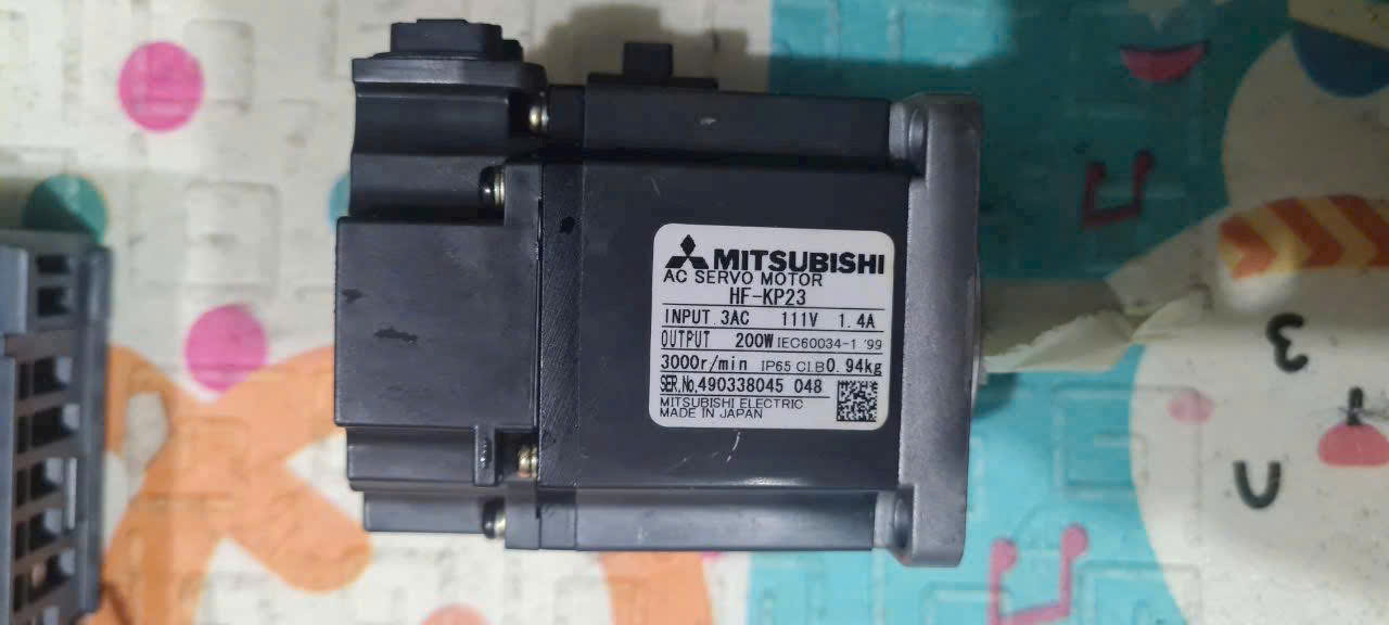
Hi everyone,I am a Master's student currently working on my thesis, which involves designing a custom, low-voltage FOC Servo Driver to control a Mitsubishi MR-J3 motor (equipped with the 18-bit absolute encoder, model J-A22/J-A24).My goal is to achieve full closed-loop control (current, speed, and position) using a custom control board. I am determined to implement the encoder decoder myself rather than using commercial converter modules, as the academic board requires a deep dive into the firmware.What I have done so far:
lap
Master's Student in Mechatronics Engineering
- Hardware Interface: I designed a custom PCB utilizing a high-speed RS-485 transceiver (MAX3485) connected to the USART peripheral of an STM32G4 MCU. The differential lines (MR/MRR) are properly terminated with a 120-ohm resistor.
- Signal Capture: I have configured the MCU's USART to run at 2.5 Mbps (8N1), utilizing DMA to handle the high-speed RX buffer without blocking the CPU.
- Prior Research: I have deeply analyzed open-source projects like STMBL and various threads on the LinuxCNC forum regarding the "Mit-A/Mit-B" protocols.
- The Request Command: I am trying to identify the exact initialization/request byte sequence that the Master needs to send to "wake up" or poll the encoder continuously. I tried sendingand
0x02
based on some older J2S documentation, but the encoder response is inconsistent.0x1A
- Frame Parsing & CRC: Once the encoder responds, I receive an 7-to-9 byte packet. I am trying to figure out how the 18-bit position data is packed across these bytes (Little-Endian shifting vs. Scrambled bits), and what specific CRC-8 polynomial (and initial value) is used to validate the frame.
lap
Master's Student in Mechatronics Engineering
Last edit: 11 Jul 2026 13:45 by vanlap02.
Please Log in or Create an account to join the conversation.
- dm17ry
-

- Offline
- Elite Member
-

Less
More
- Posts: 211
- Thank you received: 89
11 Jul 2026 15:56 #347686
by dm17ry
Replied by dm17ry on topic Seeking Guidance on Mitsubishi MR-J3 Serial Encoder Protocol (J-A22/J-A24) for M
i believe all amps start with 0x92, then 0x7a, then you can continuously poll it with 0xa2. the answer to 0xa2 is straight-forward:
int16_t abs1 = rxbuf[5] + (rxbuf[6]<<8);
uint32_t cyc1 = rxbuf[2] + (rxbuf[3]<<8) + (rxbuf[4]<<16);
abs1 is full rotations counter, cyc if within-rotation position. afair, it is left-justified to 20 bits, so with your OBA18 encoder 2 LSBs may be always 0.
the last byte of a frame is a xor checksum, not a CRC
int16_t abs1 = rxbuf[5] + (rxbuf[6]<<8);
uint32_t cyc1 = rxbuf[2] + (rxbuf[3]<<8) + (rxbuf[4]<<16);
abs1 is full rotations counter, cyc if within-rotation position. afair, it is left-justified to 20 bits, so with your OBA18 encoder 2 LSBs may be always 0.
the last byte of a frame is a xor checksum, not a CRC
The following user(s) said Thank You: NWE
Please Log in or Create an account to join the conversation.
- mark-v-d
- Offline
- New Member
-
Less
More
- Posts: 17
- Thank you received: 7
12 Jul 2026 20:02 #347718
by mark-v-d
Replied by mark-v-d on topic Seeking Guidance on Mitsubishi MR-J3 Serial Encoder Protocol (J-A22/J-A24) for M
I've made my own motordrive and used the Mitubishi encoders extensively.
I have tested several motors, from the MR-PQ, MR-MFS, MR_SFS and MR-KP
series. They all seem to use the same protocol and checksum. Some types
use full-duplex communication and others use a single bi-directional
version.
From what I have seen, it is important to poll the motor at a fixed
frequency of 4.5kHz.
My source code is available at:
github.com/mark-v-d/motor_control/blob/h...4400/src/encoder.cpp
The class mitsubishi_PQ_t is the full-duplex version of the protocol,
and mitsubishi_MFS13_t is the half-duplex implementation.
Basically start sending 0x1a at 2.5Mb/s at 4.5kHz and the encoder starts
responding. There is a checksum at the end of the packet.
I have tested several motors, from the MR-PQ, MR-MFS, MR_SFS and MR-KP
series. They all seem to use the same protocol and checksum. Some types
use full-duplex communication and others use a single bi-directional
version.
From what I have seen, it is important to poll the motor at a fixed
frequency of 4.5kHz.
My source code is available at:
github.com/mark-v-d/motor_control/blob/h...4400/src/encoder.cpp
The class mitsubishi_PQ_t is the full-duplex version of the protocol,
and mitsubishi_MFS13_t is the half-duplex implementation.
Basically start sending 0x1a at 2.5Mb/s at 4.5kHz and the encoder starts
responding. There is a checksum at the end of the packet.
The following user(s) said Thank You: NWE
Please Log in or Create an account to join the conversation.
- dm17ry
-
- Offline
- Elite Member
-
Less
More
- Posts: 211
- Thank you received: 89
12 Jul 2026 22:11 #347719
by dm17ry
Replied by dm17ry on topic Seeking Guidance on Mitsubishi MR-J3 Serial Encoder Protocol (J-A22/J-A24) for M
i believe all non-cnc encoders (OSA/OBA 14,17,18,24) answer on both MR and MD pairs simultaneously. OSA253/104/105 only answer on MD so you need to use 4 wire connection with them.
Please Log in or Create an account to join the conversation.
- LinuxCNC
- General LinuxCNC Questions
- Seeking Guidance on Mitsubishi MR-J3 Serial Encoder Protocol (J-A22/J-A24) for M
Time to create page: 0.118 seconds