First of all, GIGO, i.e. processing incorrect data, gives incorrect results.
You can also say that if you ask the wrong question, all the answers will be wrong...
Questions like who would like to do it and whether to do it are the wrong questions, especially when asking a small and non-representative group of a few active users of this forum.
The real question is: HOW NOT TO DO THIS?
And here we know the right answer - NOT like in Mach3.
Mach3 is commercial software, which means that nothing is done to make it work good, but to make the users like it, because the company's income depends on the users' satisfaction.
It works differently in free software - if someone has the time and inclination, they add a new utility, and if someone doesn't like it, they don't use it.
The only problem here is not to break anything and not to let a program with a twenty-year history suddenly start working in a way that is unpredictable for the user.
But let's get back to Mach3.
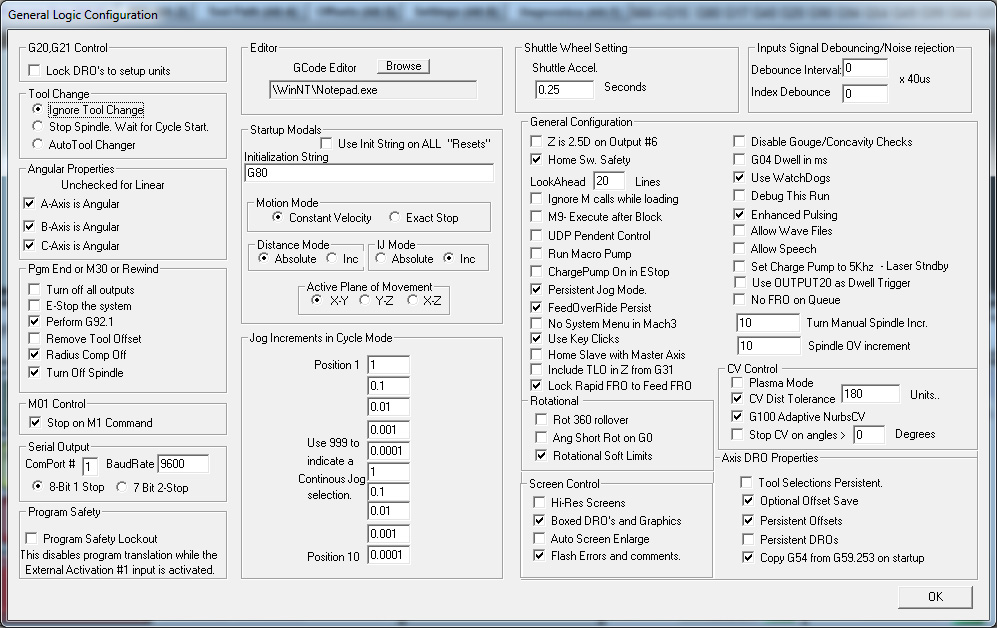
I don't have the time or inclination to look for better examples, but what I quickly found is completely enough. Here is one of the many screens for changing Mach3 settings:
Notice the "G04 dwell ms" entry in the upper right corner.
The way it works is that depending on whether this item is selected or deselected, the G04 code is interpreted in a different way. There is no need to explain the difference between 3 seconds and 3 milliseconds, and the g-code author may have no idea how his code will be executed.
Let's ignore the sobbing of the operator when his disk goes bad and he has to recreate all the windows and buttons, because that would be offtopic.
The utility we are talking about here is implemented in Mach3. AI writes about it this way:
Code:
To set up the rotation radius for your rotary (A-axis) in Mach3, enter the distance from the center of rotation to your material surface in the Settings tab.
Step-by-Step Configuration
• Enable Toolpath Settings: Go to Config > Toolpath in the top menu. Check the options for A-Rotations Enabled and use radius/feedrate correction if available. Click Save Settings.
• Set Angular Properties: Go to Config > General Config, look for Angular Properties on the left side, and check A Axis is Angular. Click OK and restart Mach3.
• Enter the Rotation Radius: Navigate to the Settings tab on the main screen. Look for the Rotation Radius (or A-radius/diameter DRO) field near the top right.
• Input Your Measurement: Type the exact radius (or half-diameter) of your current workpiece material into the A-axis box and press ENTER. For example, if your stock is 2 inches across, enter 1.0. (If your Z-zero is set directly at the center of rotation, enter a very small nominal value like 0.001).
• Verify the Setup: Return to the Program Run tab. Check that the Radius Correct LED indicator next to the A-axis display turns lit/yellow, which confirms Mach3 is properly using the radius to calculate coordinated feedrates and graphics. Remember to update this value whenever you change stock sizes.
Basically everything is true.
Let's not do the same in LinuxCNC.
The definition of g-code is that it is a description of the tool path and let's stick to it.
The same g-code should be executed in the same way on different machines, and not on each machine differently because the operator changed something in settings...

 Topic Author