5i25 + 7i85s +....
- casetero
- Offline
- Senior Member
-

Less
More
- Posts: 44
- Thank you received: 1
02 Jun 2016 12:18 #75325
by casetero
Replied by casetero on topic 5i25 + 7i85s +....
Hi,
Im testing the system, but i dont know what is the name my pins of the 5i25.
I want to use the A,B,INDEX of ENC3 of my 7i85s, how can i call them in the HAL file?
Thank you.
Im testing the system, but i dont know what is the name my pins of the 5i25.
I want to use the A,B,INDEX of ENC3 of my 7i85s, how can i call them in the HAL file?
Thank you.
Please Log in or Create an account to join the conversation.
- andypugh
-

- Offline
- Moderator
-

Less
More
- Posts: 19875
- Thank you received: 4642
02 Jun 2016 12:55 #75328
by andypugh
Replied by andypugh on topic 5i25 + 7i85s +....
Why do you want A, B and index in HAL? You don't normally need to look at the encoder inputs in HAL, you look instead at the encoder counts and position HAL pins.
Please Log in or Create an account to join the conversation.
- Todd Zuercher
-

- Away
- Platinum Member
-

Less
More
- Posts: 4757
- Thank you received: 1459
02 Jun 2016 13:02 #75329
by Todd Zuercher
Replied by Todd Zuercher on topic 5i25 + 7i85s +....
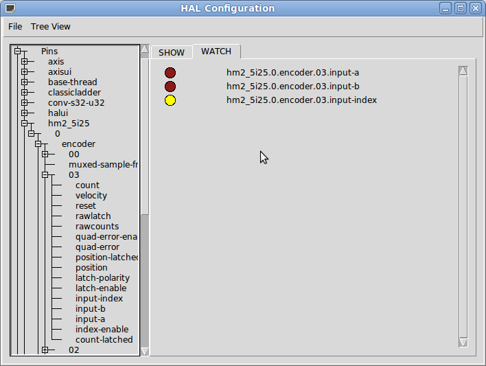
You can look at the pins using Show HAL Configuration.
Please Log in or Create an account to join the conversation.
- Todd Zuercher
-
- Away
- Platinum Member
-
Less
More
- Posts: 4757
- Thank you received: 1459
02 Jun 2016 13:21 #75330
by Todd Zuercher
Replied by Todd Zuercher on topic 5i25 + 7i85s +....
If you were wanting to use these as GPIO it is a little more complicated, because the 7i85 reads the encoders with a mux to save pins. It is reading 12 encoder pins (3pins X 4 encoders) using only 7 pins from the 5i25 port. The rest of the pins in the 5i25 port are your 8 step/dir pins, and 2 for the Smart Serial port.
Please Log in or Create an account to join the conversation.
- PCW
-

- Offline
- Moderator
-
Less
More
- Posts: 17976
- Thank you received: 5275
02 Jun 2016 14:11 #75334
by PCW
Replied by PCW on topic 5i25 + 7i85s +....
Ability to use muxed encoder pins as general purpose inputs
was one reason the A,B.INDEX input pins were added to the encoder driver
Normally you would set the inputs to TTL mode
The encoder inputs are then TTL compatible with a 2K pullup to 5V
was one reason the A,B.INDEX input pins were added to the encoder driver
Normally you would set the inputs to TTL mode
The encoder inputs are then TTL compatible with a 2K pullup to 5V
Please Log in or Create an account to join the conversation.
- casetero
- Offline
- Senior Member
-
Less
More
- Posts: 44
- Thank you received: 1
06 Jun 2016 16:46 #75560
by casetero
Replied by casetero on topic 5i25 + 7i85s +....
Hi again,
Ive been fighting with the 7i85s posibilities and finally i got my system working properly. Linuxnc is able to know which limit is being activated allowing the movement in the right direction of the axis, and not allowing in the wrong direction.
The 7i85s, as PCW said, can handle these PINS as GPIO´s too. It works fine.
PCW i will send you and email requesting you a Spin1x right now.
Thank you all.
Please Log in or Create an account to join the conversation.
- casetero
- Offline
- Senior Member
-
Less
More
- Posts: 44
- Thank you received: 1
07 Jun 2016 09:15 #75612
by casetero
Replied by casetero on topic 5i25 + 7i85s +....
I´ve realized that i can make the purchase of the card via web.
Do i need any special connector or cable to link the spin1x to my system?
I need to know it to purchase all the items i need for my purpose.
Thank you all.
Do i need any special connector or cable to link the spin1x to my system?
I need to know it to purchase all the items i need for my purpose.
Thank you all.
Please Log in or Create an account to join the conversation.
- PCW
-
- Offline
- Moderator
-
Less
More
- Posts: 17976
- Thank you received: 5275
07 Jun 2016 16:17 #75645
by PCW
Replied by PCW on topic 5i25 + 7i85s +....
No special connector needed but you do need 3 output bits:
PWM
ENA
DIR
(or 2 if you dont need to reverse)
PWM
ENA
DIR
(or 2 if you dont need to reverse)
Please Log in or Create an account to join the conversation.
- casetero
- Offline
- Senior Member
-
Less
More
- Posts: 44
- Thank you received: 1
09 Nov 2016 10:59 #82604
by casetero
Replied by casetero on topic 5i25 + 7i85s +....
Hi again,
Im going to wire my SPIN1X. I have some doubts at respect.
I have to supply the SPIN1X with 5V, independently of which is my reference voltage of my VFD is ( in this case 10V), havent i??
If this is true, where do i have to wire my VFD reference voltage?? I suposse is 10 V to SP+ and 0 V to SP- , but as i see in the manual of the SPIN1X these are output PINS, so im confused.
In the manual of my VFD i have one PIN that says " Output power supply of frequency reference". I suppose this will go to SP+.
I have another PIN that says " Common Value of frequency reference". I suppose this will go to SP-.
And another PIN that says " Input of frequency reference". I suppose this will go to SPV.
Am i correct??
Thank you very much!!
Please Log in or Create an account to join the conversation.
- andypugh
-
- Offline
- Moderator
-
Less
More
- Posts: 19875
- Thank you received: 4642
09 Nov 2016 11:24 #82605
by andypugh
Replied by andypugh on topic 5i25 + 7i85s +....
Just wire as described in the VFD manual, treating CCW+ and CCW- as a reverse push-button, CW+ and CW- as a forward button and ENA+ ansd ENA- as an ON switch. Then SP+, SP- and SPV are wired in the same place as a speed potentiometer.
Unlike a physical button, the polarity of the switch outputs matters.
Unlike a physical button, the polarity of the switch outputs matters.
Please Log in or Create an account to join the conversation.
Moderators: cmorley
Time to create page: 0.173 seconds