- Configuring LinuxCNC
- Configuration Tools
- PnCConf Wizard
- 7i76e pin configuration, flash firmware, do it in HAL files, etc. ???
7i76e pin configuration, flash firmware, do it in HAL files, etc. ???
- mlw19mlw91
- Offline
- Junior Member
-

Less
More
- Posts: 23
- Thank you received: 2
05 Nov 2021 23:31 #225448
by mlw19mlw91
Replied by mlw19mlw91 on topic 7i76e pin configuration, flash firmware, do it in HAL files, etc. ???
Cool that makes sense! I should have thrown in here that there's also all three axes motor drives that have the two wire outputs for the ready signal, so 4 sets total. Not sure there's enough serial ports for that but I'll look.
One weird thing about this machine is it has an index signal, and not an encoder signal, for each axis to make sure it's in sync. If it didn't detect the pulse when it knew it should it would throw an error. Not the best of setups as it only happens once per ball screws revolution. But better than nothing. It's a three wire sensor, I can't remember the name but it senses when this piece of metal (or magnet) moves by.
It also seemed to use these in the homing sequence. It would hit the limit switch then back off until it got that pulse.
Would this require custom programming or could I somehow set this up as an encoder?
Please Log in or Create an account to join the conversation.
- rodw
-

- Offline
- Platinum Member
-

Less
More
- Posts: 11967
- Thank you received: 4078
06 Nov 2021 00:00 #225451
by rodw
Replied by rodw on topic 7i76e pin configuration, flash firmware, do it in HAL files, etc. ???
I'm glad you came here and I see the experts have been helping out.
With less than simple system to set up you really need to edit your ini and hal files yourself as pncconf is just for a basic config.
Think of it as the ini files defines the fixed part of your machine that does not change and the hal file is where you "wire up" the machine to Linuxcnc which often accesses the data in the ini file.
With regard homing, its covered here
linuxcnc.org/docs/devel/html/config/ini-homing.html
Take your time here to understand it.
You should not need custom programming but if you understand C its easy to write your own components.
See linuxcnc.org/docs/devel/html/hal/comp.html
You may need to do some work in hal to work for your hardware. Eventually it will all click.
But the first task now is to work with PCW to get your motors moving!
The following user(s) said Thank You: mlw19mlw91
Please Log in or Create an account to join the conversation.
- rodw
-
- Offline
- Platinum Member
-
Less
More
- Posts: 11967
- Thank you received: 4078
06 Nov 2021 00:46 #225457
by rodw
Replied by rodw on topic 7i76e pin configuration, flash firmware, do it in HAL files, etc. ???
Actually, I was thinking afterwards that you probably don't need to worry about the index signal when homing. That probably only had value to the old controller. To start with, set the machine up for immediate homing per the docs so you can home the machine and check it moves then set the homing up later using linuxcnc's normal homing sequence without an index. Just make sure when a home switch is triggered, it stays triggered until the end of travel.
The following user(s) said Thank You: mlw19mlw91
Please Log in or Create an account to join the conversation.
- mlw19mlw91
- Offline
- Junior Member
-
Less
More
- Posts: 23
- Thank you received: 2
07 Nov 2021 22:00 #225590
by mlw19mlw91
Replied by mlw19mlw91 on topic 7i76e pin configuration, flash firmware, do it in HAL files, etc. ???
Thanks for the help guys!!
one thing I think might work, I can assign the same pins the same fuctions, right? I may just assign a stepper motor output with a spindle direction signal. Any time the spindle is moving, it has a direction, and so the spindle should be enabled. That would solve the spindle enable problem pretty easily. I am not sure what might happen if I send a signal inverted to what it normally is to these pins on the VFD (the enable pins on VFD are differential signal 5V, is there a chance an inverted signal could be bad?)
I'll take your approach on the homing Rod, I don't know C at this time. I really want to make it perfect! (or like it worked from the factory) However I'm not able to dive so deep into it at this time. I really see setting all of this up as a good skill to have so I'll put a list of finishing touches on the back burner I think and develop these skills as I go.
So for now the only thing I'm worried about then is the spindle (stepper motors already figured out) and then just wiring up the limit switches, door switch, E stop.
The following user(s) said Thank You: rodw
Please Log in or Create an account to join the conversation.
- mlw19mlw91
- Offline
- Junior Member
-
Less
More
- Posts: 23
- Thank you received: 2
14 Nov 2021 23:55 #226526
by mlw19mlw91
Replied by mlw19mlw91 on topic 7i76e pin configuration, flash firmware, do it in HAL files, etc. ???
Today I had an odd but short lived success controling the spindle.
I hooked everythingn up basically as you would think you would for pins 1-4, except using a breadboard and 5V power adapter.
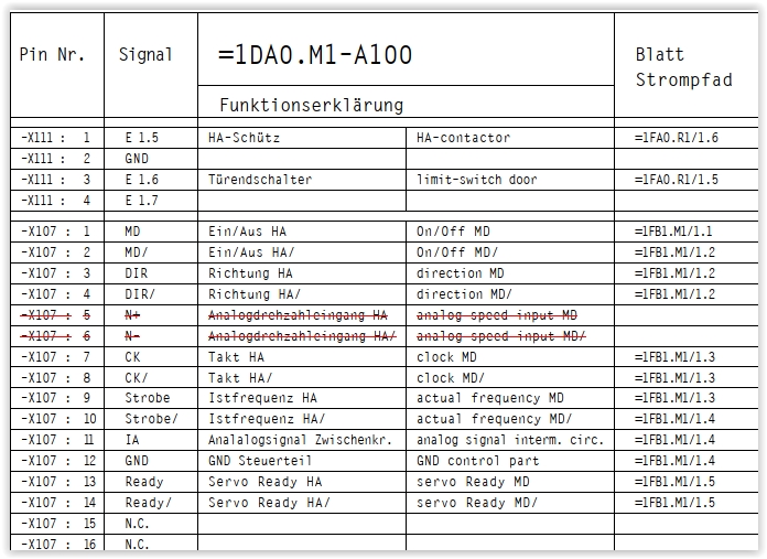
So what happened was I hooked pin 11 (IA, analog signal interm. circ) to positive and pin 12 (GND control part) to gnd / 0V. I had the positive on my linear variable power supply. As I increased the voltage, the spindle speed increased. Except I never got anywhere close to maximum spindle speed by about 10V, and shortly after 10V the VFD shut down and indicated an error. Analog speed input MD and MD/ (pins 5 and 6) were disconnected and connecting them and/or other wires did not seem to make any kindof a difference in regards to the maximum speed achieved by the spindle.
Very odd, let me know if you have any ideas! I'm going to sleep on it and if I can't figure it out I'm going to get a new VFD tomorrow. I figure I'd prefer a USB controllable VFD anyway because they transmit the PC some cool information, is that right? I can see amps and other statistics?
I hooked everythingn up basically as you would think you would for pins 1-4, except using a breadboard and 5V power adapter.
So what happened was I hooked pin 11 (IA, analog signal interm. circ) to positive and pin 12 (GND control part) to gnd / 0V. I had the positive on my linear variable power supply. As I increased the voltage, the spindle speed increased. Except I never got anywhere close to maximum spindle speed by about 10V, and shortly after 10V the VFD shut down and indicated an error. Analog speed input MD and MD/ (pins 5 and 6) were disconnected and connecting them and/or other wires did not seem to make any kindof a difference in regards to the maximum speed achieved by the spindle.
Very odd, let me know if you have any ideas! I'm going to sleep on it and if I can't figure it out I'm going to get a new VFD tomorrow. I figure I'd prefer a USB controllable VFD anyway because they transmit the PC some cool information, is that right? I can see amps and other statistics?
Attachments:
Please Log in or Create an account to join the conversation.
Moderators: cmorley
- Configuring LinuxCNC
- Configuration Tools
- PnCConf Wizard
- 7i76e pin configuration, flash firmware, do it in HAL files, etc. ???
Time to create page: 0.261 seconds