7i76E Spindle configuration
- unknown
- Offline
- Platinum Member
-

Less
More
- Posts: 888
- Thank you received: 325
18 Sep 2025 21:41 #335173
by unknown
Replied by unknown on topic 7i76E Spindle configuration
The OP was supplied with a config as requested for 4axis and a spindle, to 24k I think, by PCW. Even with is he could not get an output, taking this into account PncCONF is not the issue.
If the OP could be so kind as to supply a picture of the wiring of the actual spindle connector and a diagram as well of how he wired it I think that would be quite helpful. This is the second time I have made this request.
To OP seems to have missed or ignored the bit about PWM not being involved in configuring the spindle.
Just making a guess I suspect that spindle + and spindle - are not being supplied with an isolated voltage. If this is the case spindle out with not have a voltage that is in line with the selected spindle speed.
Wiring of the opto isolated outputs can be tackled later.
To reiterate the OP has a config supplied by PCW, which we can take as being gospel and if the board is wired correctly will work.
For testing I would not have the spindle connected, I would just be monitoring the spindle output with a multimeter referenced to spindle - .
This is actually how I went setting up my spindle, but using a smart serial board as I required the servo driver to be some distance from my 7i76 and did not want a small analogue voltage being transmitted over a long cable. Paranoia may have had been high that day.
The following user(s) said Thank You: RobotMatic
Please Log in or Create an account to join the conversation.
- PCW
-

- Offline
- Moderator
-

Less
More
- Posts: 17917
- Thank you received: 5246
18 Sep 2025 22:12 #335174
by PCW
Replied by PCW on topic 7i76E Spindle configuration
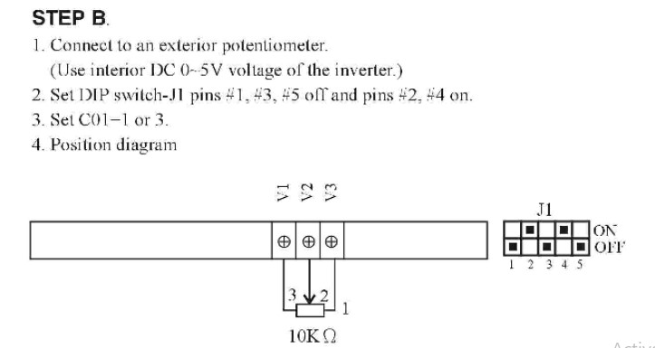
There is no tension on pins (1-2) (1-3) of the TB4
That means no Spindle output is possible.
The 7I76/7I76E/7I76EU do not supply the 10V.
The spindle output on these cards works as a
potentiometer. Typically the 10V is supplied by
the VFD.
That means no Spindle output is possible.
The 7I76/7I76E/7I76EU do not supply the 10V.
The spindle output on these cards works as a
potentiometer. Typically the 10V is supplied by
the VFD.
The following user(s) said Thank You: RobotMatic
Please Log in or Create an account to join the conversation.
- RobotMatic
-
 Topic Author
- Offline
- Elite Member
-

Less
More
- Posts: 199
- Thank you received: 25
18 Sep 2025 22:36 #335175
by RobotMatic
Replied by RobotMatic on topic 7i76E Spindle configuration
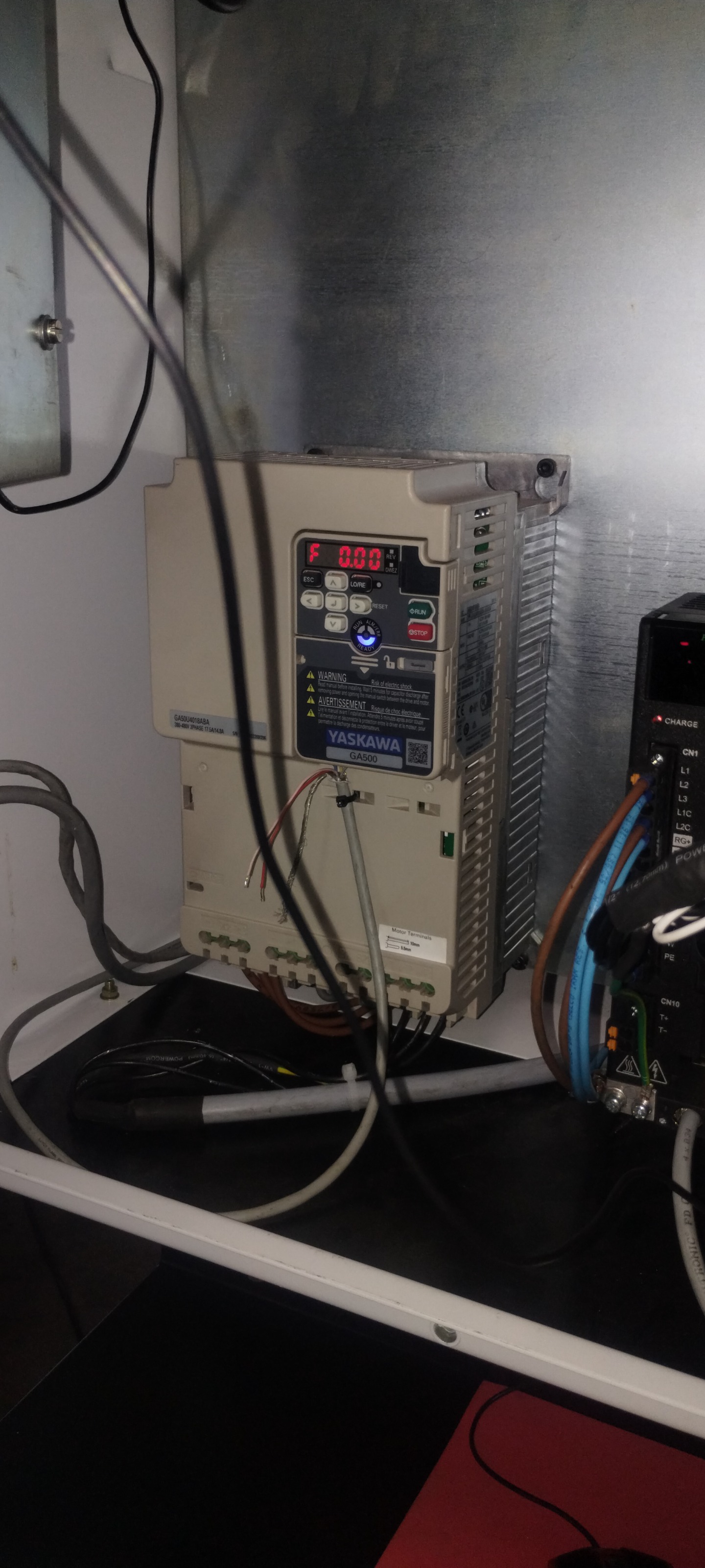
Thank you all for the responses. The VFD GA500 is already installed in the machine and I don’t have it here. I have an LS600 on my work desk which I am using for the tests. I will try to send you the information you are requesting as soon as possible.
PCW !. Thank you for coming back! From the heart!
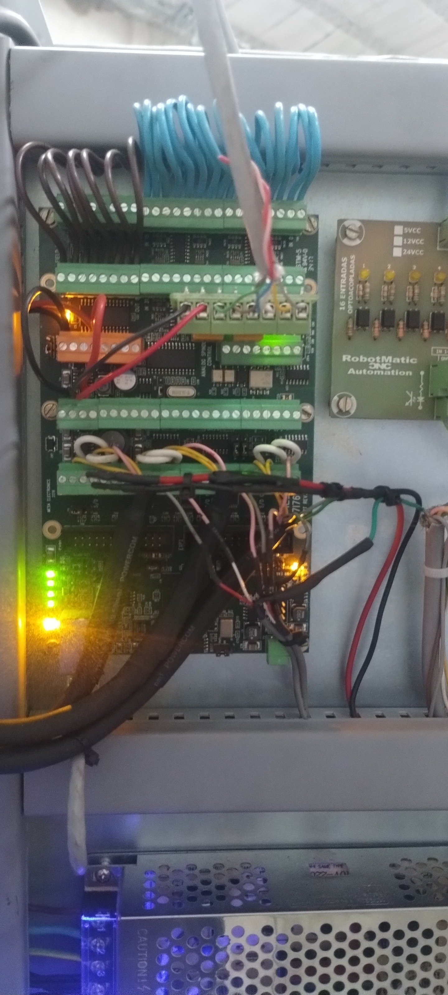
I advance the board that I am using in the TB4 connector, I believe, as PCW explains, that I am not supplying the 10vcc. I am going to check the LS600.
PCW !. Thank you for coming back! From the heart!
I advance the board that I am using in the TB4 connector, I believe, as PCW explains, that I am not supplying the 10vcc. I am going to check the LS600.
Please Log in or Create an account to join the conversation.
- RobotMatic
-
Topic Author
- Offline
- Elite Member
-
Less
More
- Posts: 199
- Thank you received: 25
18 Sep 2025 22:54 #335176
by RobotMatic
Replied by RobotMatic on topic 7i76E Spindle configuration
PncConf works in Live!!!!! it was the language !!!!!!!!!! I am very happy!!!! thank you!!!!!!!!
I continue now with the VFD!!!
Thank you!!!!!!!!!!
I continue now with the VFD!!!
Thank you!!!!!!!!!!
The following user(s) said Thank You: tommylight
Please Log in or Create an account to join the conversation.
- RobotMatic
-
Topic Author
- Offline
- Elite Member
-
Less
More
- Posts: 199
- Thank you received: 25
19 Sep 2025 00:24 - 19 Sep 2025 00:32 #335179
by RobotMatic
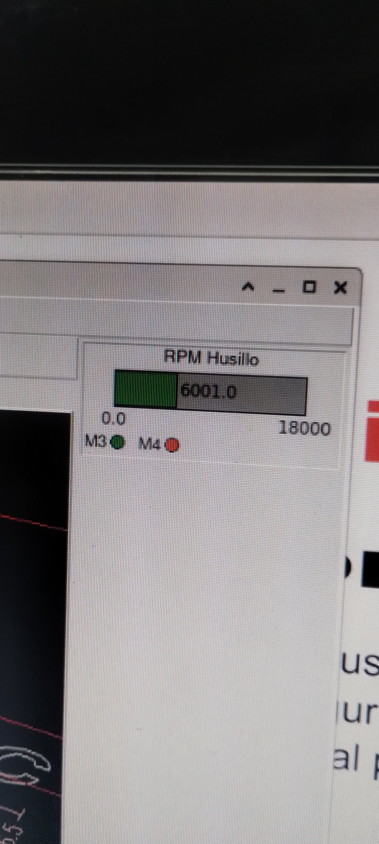
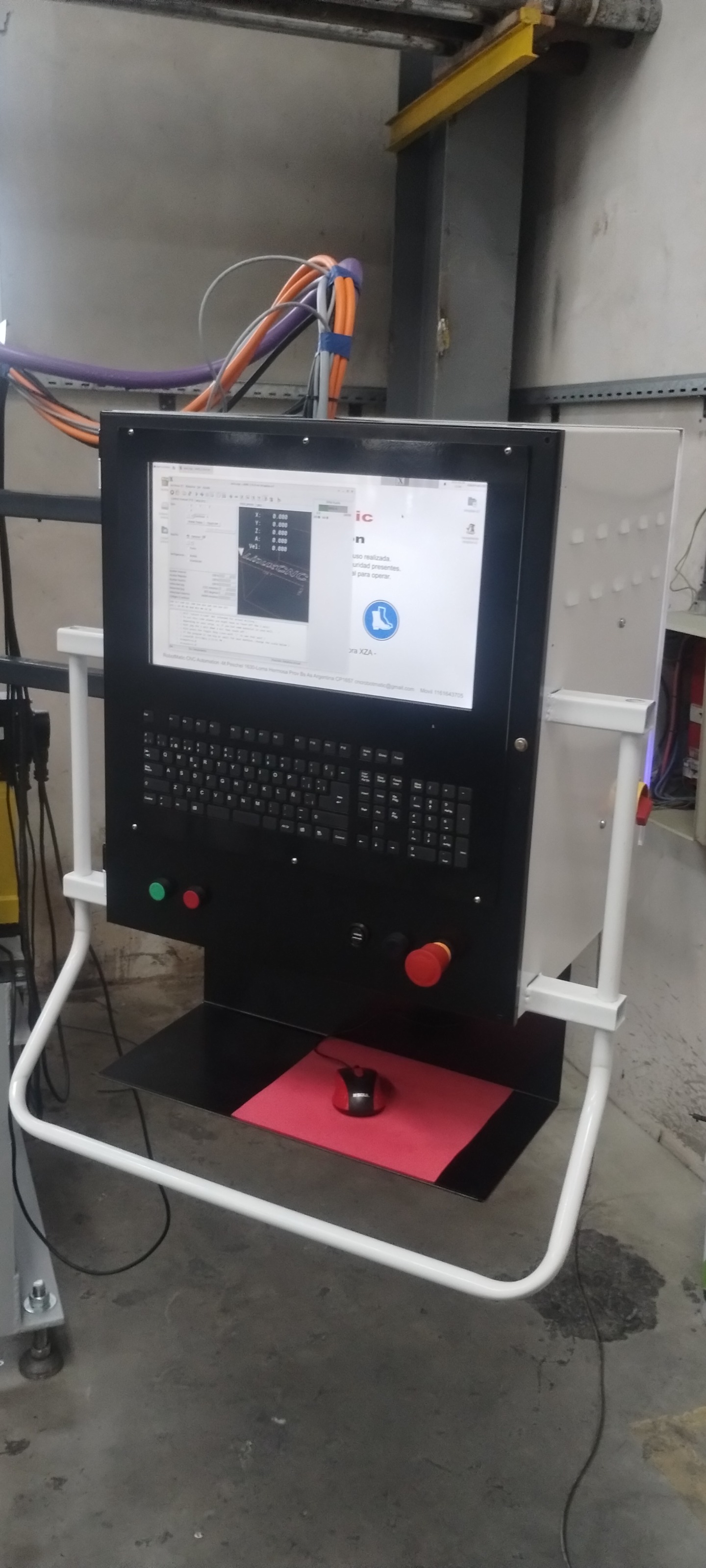
It works!!!! The VFD was not sending the voltage!!!.PCW ,Tommyligth,unknowm !!! thank you very much from the heart!!!He learned a great lesson today!! it works !!
Replied by RobotMatic on topic 7i76E Spindle configuration
It works!!!! The VFD was not sending the voltage!!!.PCW ,Tommyligth,unknowm !!! thank you very much from the heart!!!He learned a great lesson today!! it works !!
Attachments:
Last edit: 19 Sep 2025 00:32 by RobotMatic.
The following user(s) said Thank You: tommylight, Clive S
Please Log in or Create an account to join the conversation.
- tommylight
-

- Away
- Moderator
-
Less
More
- Posts: 21630
- Thank you received: 7384
19 Sep 2025 00:55 #335181
by tommylight
Replied by tommylight on topic 7i76E Spindle configuration
Why is your DVM on the floor ??? ")
The following user(s) said Thank You: RobotMatic
Please Log in or Create an account to join the conversation.
- RobotMatic
-
Topic Author
- Offline
- Elite Member
-
Less
More
- Posts: 199
- Thank you received: 25
19 Sep 2025 12:30 #335187
by RobotMatic
Replied by RobotMatic on topic 7i76E Spindle configuration
I need to work more organized!!
Thank you for all the help you gave me!!! I am going out to configure the VFD so I can finish the machine, I am under a lot of pressure!! Thank you!!!!!
Thank you for all the help you gave me!!! I am going out to configure the VFD so I can finish the machine, I am under a lot of pressure!! Thank you!!!!!
Please Log in or Create an account to join the conversation.
- RobotMatic
-
Topic Author
- Offline
- Elite Member
-
Less
More
- Posts: 199
- Thank you received: 25
20 Sep 2025 00:18 #335203
by RobotMatic
Replied by RobotMatic on topic 7i76E Spindle configuration
Attachments:
The following user(s) said Thank You: tommylight
Please Log in or Create an account to join the conversation.
- PCW
-
- Offline
- Moderator
-
Less
More
- Posts: 17917
- Thank you received: 5246
20 Sep 2025 01:03 #335205
by PCW
Replied by PCW on topic 7i76E Spindle configuration
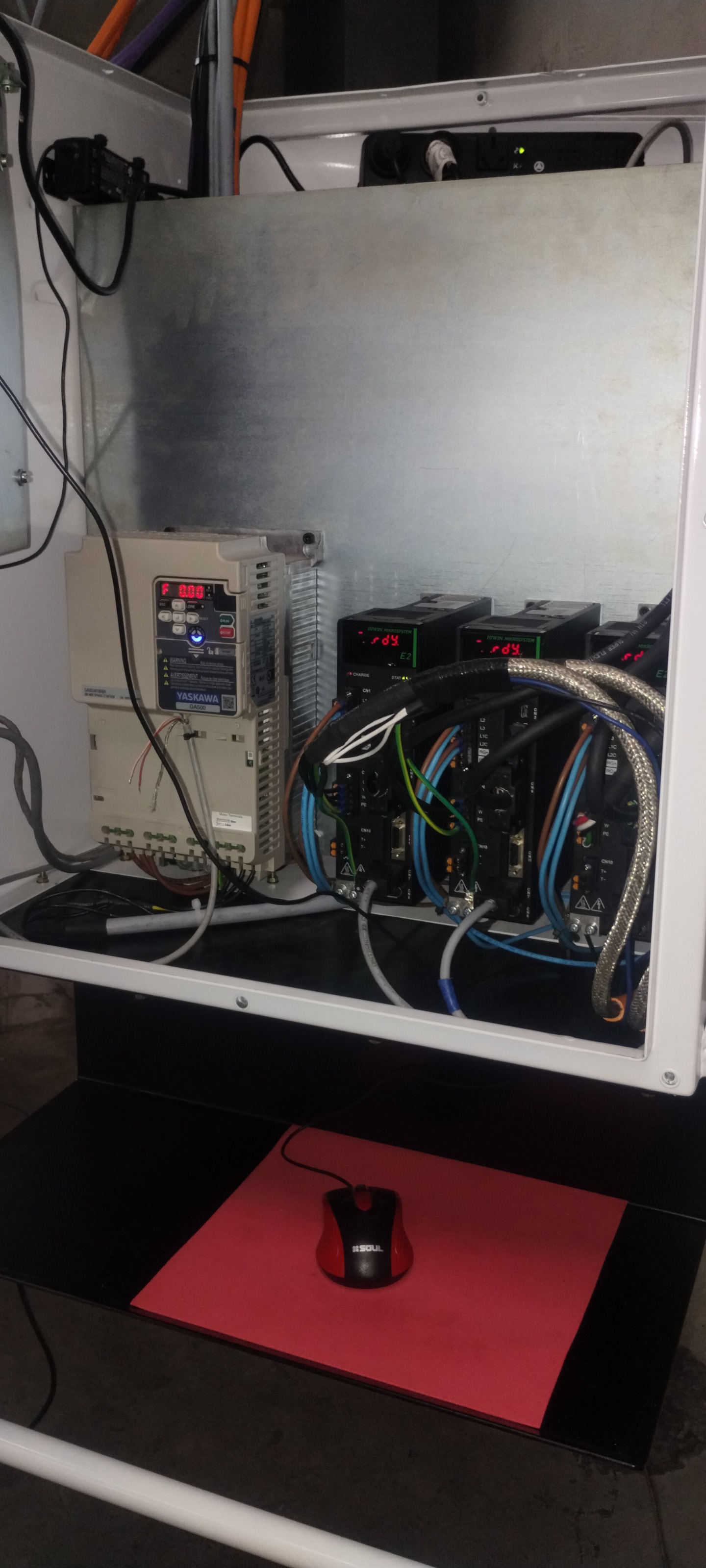
I'm a bit concerned about the STEP/DIR wiring.
It appears that the thick white wires are grounding the STEP- and DIR- pins
This should never be done as it shorts out the STEP- and DIR- pins
possible damaging the driver chip.
If STEP- / DIR- are unused, they should be left unconnected.
It appears that the thick white wires are grounding the STEP- and DIR- pins
This should never be done as it shorts out the STEP- and DIR- pins
possible damaging the driver chip.
If STEP- / DIR- are unused, they should be left unconnected.
The following user(s) said Thank You: RobotMatic
Please Log in or Create an account to join the conversation.
- RobotMatic
-
Topic Author
- Offline
- Elite Member
-
Less
More
- Posts: 199
- Thank you received: 25
20 Sep 2025 12:00 #335209
by RobotMatic
Replied by RobotMatic on topic 7i76E Spindle configuration
I am going to check the connection, I should have connected TB2 pin 2-4 with the white wires [ Pulse - ] [ Dir - ] from the Driver.
the pink cable from the X connector seems to enter pin 2, I need to check!!
thank you very much for the observation !!!!!!!!!!
the pink cable from the X connector seems to enter pin 2, I need to check!!
thank you very much for the observation !!!!!!!!!!
Please Log in or Create an account to join the conversation.
Moderators: cmorley
Time to create page: 0.344 seconds