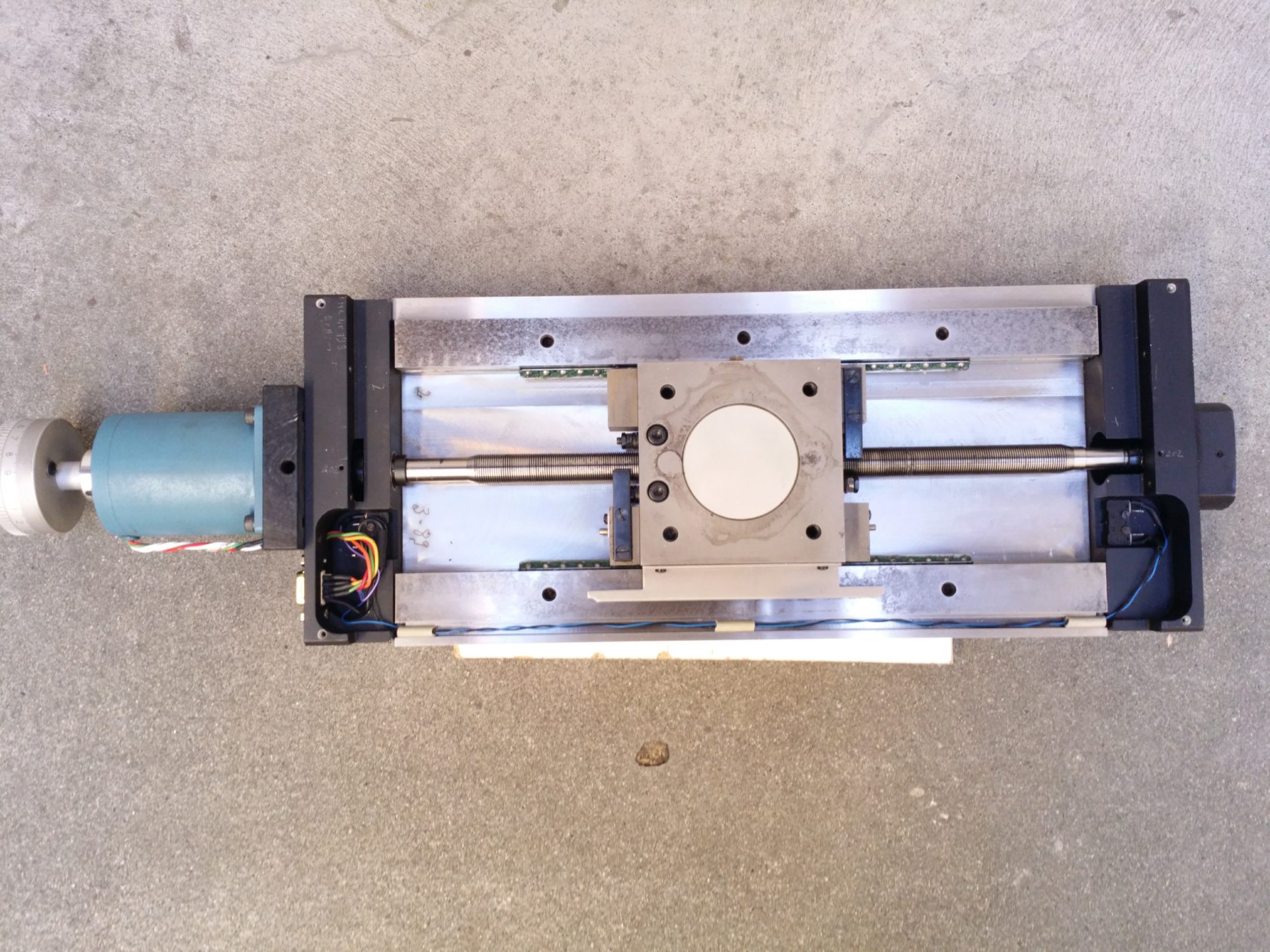
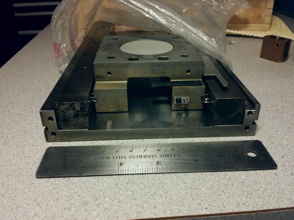
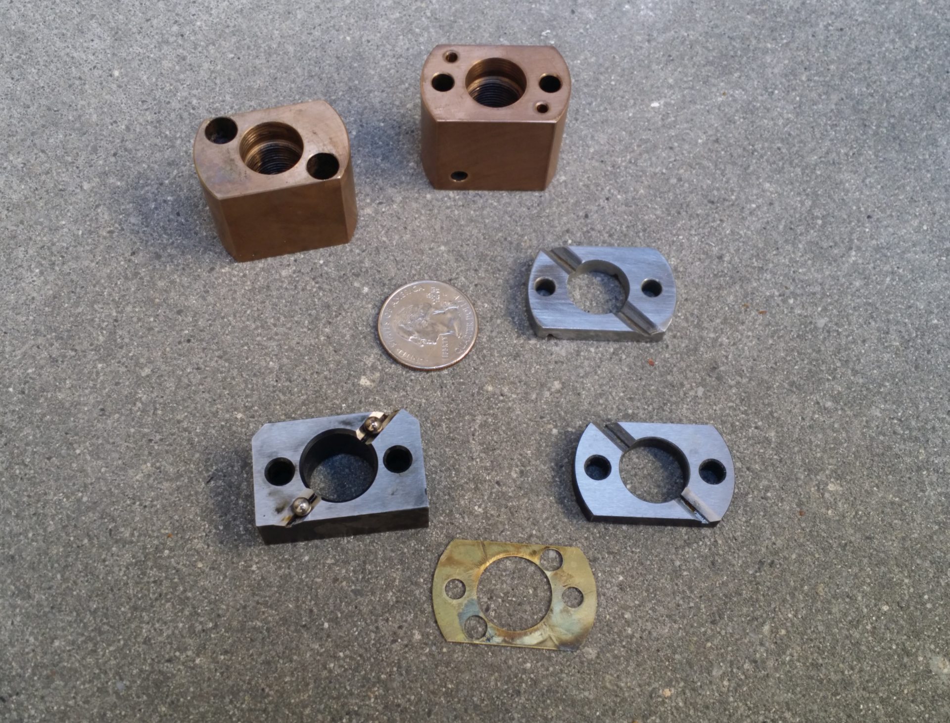
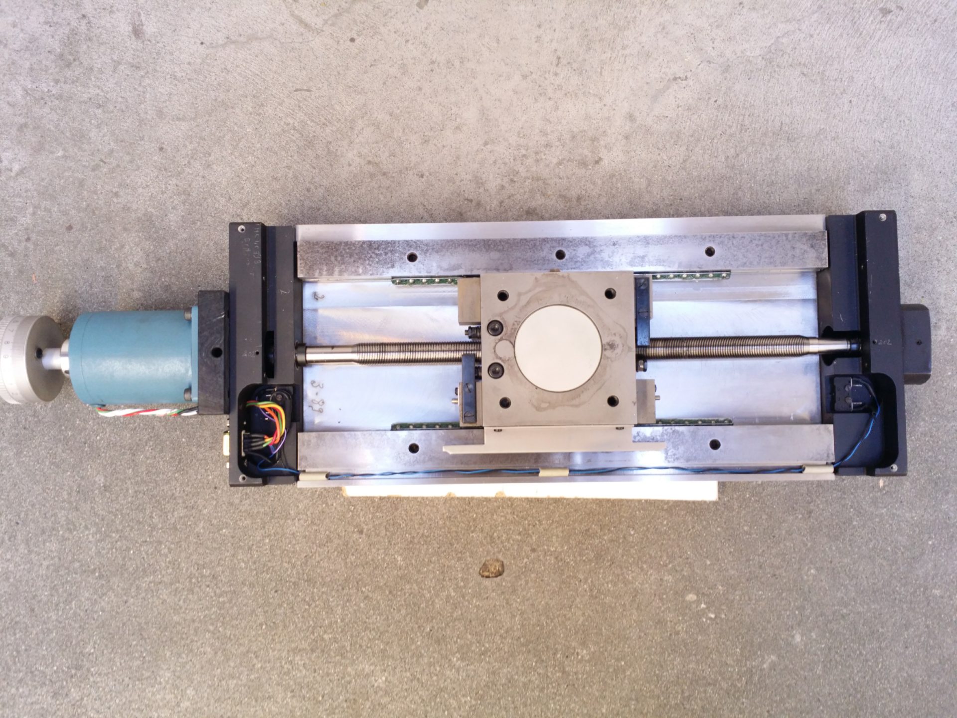
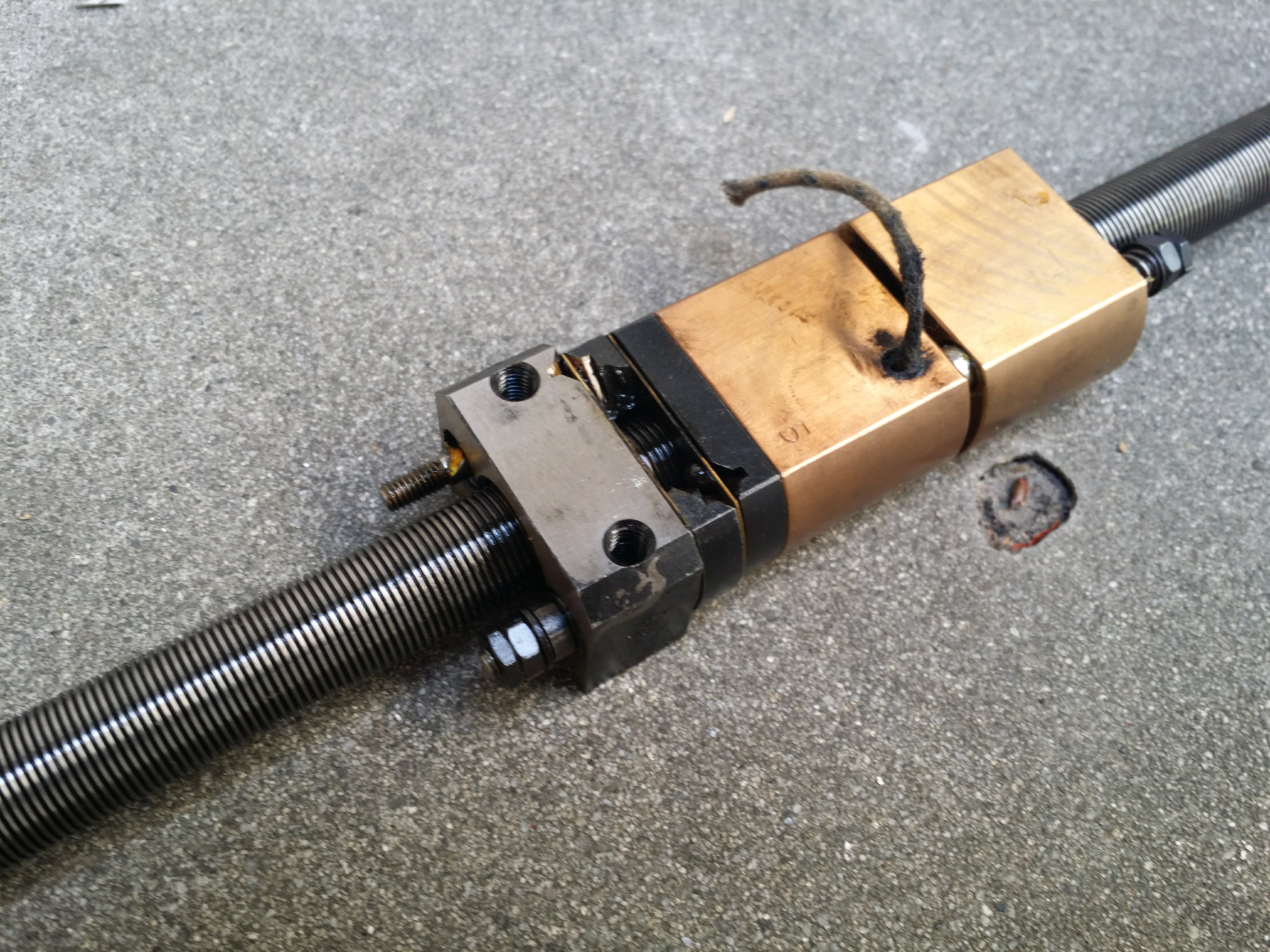
I have 2 axis; they are part of a wafer inspection microscope. The axis was made from ground wireEDM'ed tool steel. Originally the axis had wicks and a tank for lubrication. The leadnut had sliders to decouple its radial motion from its axial motion. In the photo, one of the sliders was broken, so I tried my best to make a new one from oil-hardening tool steel. Still, you can just see the bearings. The axis is stained, but it still seems to work pretty good.
The screw is 1mm.
The original motors were 200 step motors.
The units came with a 4:1 reduction drive.
There was hardware to run this closed-loop with microstepping, with photointeruppters, which were to the best of my recollection 4x.
The unit originally were set up for 0.0003125mm steps, or 0.0000123031(4960629921)".
I dumbed them down a little by installing .36 degree motors to .0001mm without microstepping.
From here, you need piezo manipulators, anti-vibration table, and yes, likely heating.
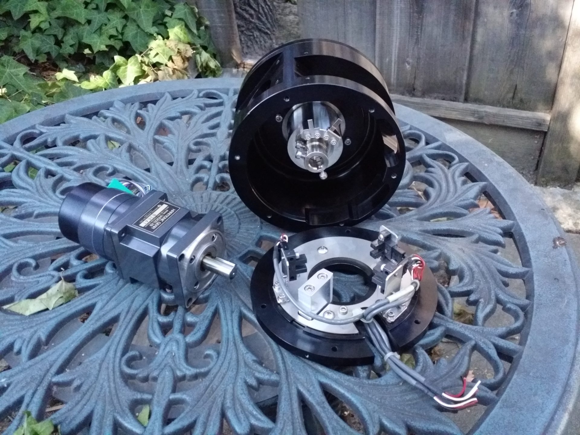
I also have some harmonic drives which are 50,000 steps per revolution.
From my perspective, there are people on this forum who want me to finish this design. I am time constrained, and I am not sure if truncating the digits will give me a full button width, and I don't know what controls universal to most machines need to go there. Functionally, I don't see a problem with the way it is.
The nail in the coffin is: the digits can't be much taller without hitting the ABS/Rel/DTG indicators, which I feel need to be there for safety.
Or, if you look at pragmatically, if I am designing this interface, would I not also make it inclusive to my needs?
I am looking at time VS benefit, and while you may not see the need for that much accuracy, I don't see the benefit to change it.
I appreciate it being brought to my attention. If I get desperate for space, perhaps I can shave a digit or two off, but it looks like 4 or more digits would have to go for another button row.