Laser power scaling based on speed and direction
- iforce2d
- Offline
- Senior Member
-

Less
More
- Posts: 44
- Thank you received: 17
09 Oct 2024 22:49 #311680
by iforce2d
Laser power scaling based on speed and direction was created by iforce2d
Recently I have been playing around with a cheap laser module, and found myself wanting to scale the power based on speed and direction. The reason for scaling with speed should be obvious. The reason for scaling with direction is that the laser beam is kinda rectangular and therefore cuts more effectively along one axis than the other - seems to be common with these cheap diode lasers.
I know there is already a component to handle some of these requirements, but I wanted to try making my own. Here is what I came up with:
One nice side effect is that I can now pause the job at any point and the laser will turn off, and resuming from the middle of a cut works nicely too. Previously I had to be careful to only pause between cuts, otherwise the laser would stay on!
Here is an example .hal file to use the component. This assumes that laser power is controlled by setting spindle speed, and is expressed in gcode as a value between 0 and 100 (eg. M3 S95). For my machine the desired final output is a value between 0 and 65535 so I'm using a lincurve to map to that range, you can remove or change that as appropriate for your case. This example also assumes that joint0 and joint1 have a trivkins type relation to movement in the X and Y axes respectively.
The current speed in each axis is obtained from joint.N.vel-cmd which might not be the actual speed, but it doesn't matter because all we need is the ratio between x/y to know the direction. My laser cuts more effectively in Y than X, so this configuration will scale the power down for Y movements. Swap the X and Y vel-cmd if your laser is the other way around. The value of 0.75 for 'share' comes from some experimentation to see how much a cut with pure Y movement needed to be scaled down to give the same cut effectiveness as a pure X movement. A value of 1 will result in no scaling.
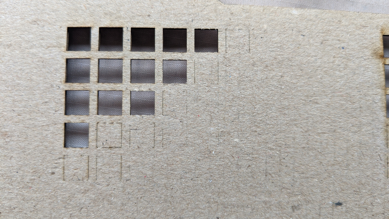
Some examples of the outcome. First, the result without using any power compensation:
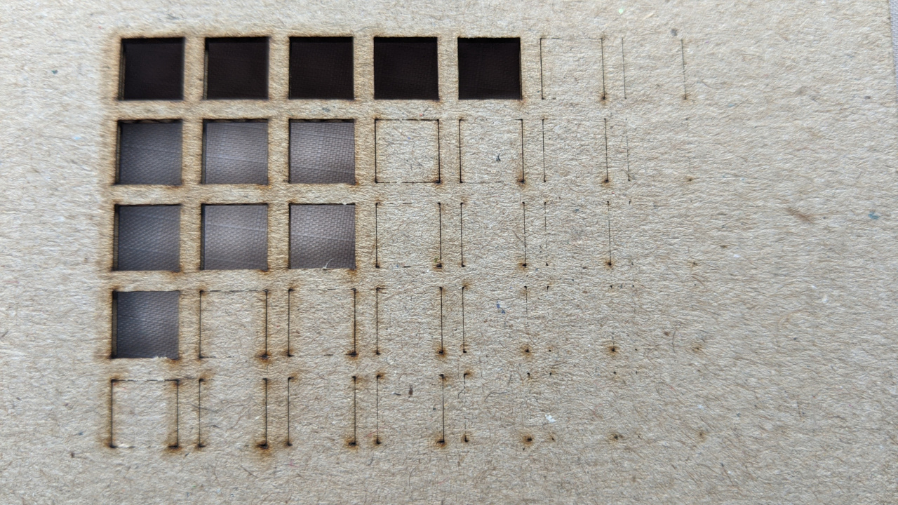
With speed compensation only:
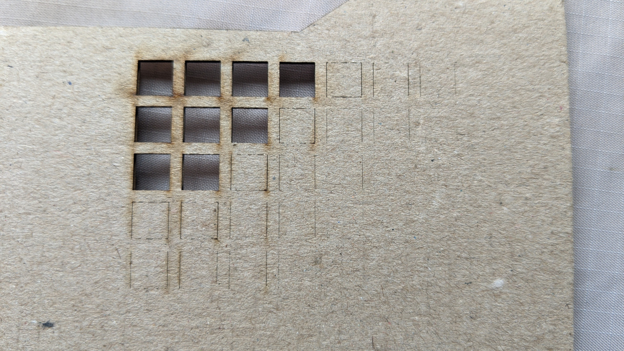
With speed and direction compensation (could still use a little less power in Y moves):
I know there is already a component to handle some of these requirements, but I wanted to try making my own. Here is what I came up with:
component laserreg "";

pin in   float inpower    "Desired laser power at constant speed";
pin in   float reqspd    "Requested speed, connect to motion.requested-vel";
pin in   float curspd    "Current speed, connect to motion.current-vel";
pin in   float velx    "Current speed x component, connect to joint.0.vel-cmd";
pin in   float vely    "Current speed y component, connect to joint.1.vel-cmd";
pin in   float share    "Fraction of power given to pure Y movement, eg. 0.6";
pin out  float outpower "Scaled output laser power";

function _ fp "Update the laser power";

license "GPL";

;;

#include <math.h>

FUNCTION(_) {

    outpower = inpower * (curspd / reqspd);

    float angle = atan2(fabs(velx), fabs(vely));  // angle away from y in radians
    float horz = angle / (0.5*M_PI);          // 1 when moving perfectly along x axis
    outpower *= share + (1-share) * horz;

    if ( outpower > inpower )
        outpower = inpower;
    if ( outpower > 100 )
        outpower = 100;
    if ( outpower < 0 )
        outpower = 0;

}
One nice side effect is that I can now pause the job at any point and the laser will turn off, and resuming from the middle of a cut works nicely too. Previously I had to be careful to only pause between cuts, otherwise the laser would stay on!
Here is an example .hal file to use the component. This assumes that laser power is controlled by setting spindle speed, and is expressed in gcode as a value between 0 and 100 (eg. M3 S95). For my machine the desired final output is a value between 0 and 65535 so I'm using a lincurve to map to that range, you can remove or change that as appropriate for your case. This example also assumes that joint0 and joint1 have a trivkins type relation to movement in the X and Y axes respectively.
The current speed in each axis is obtained from joint.N.vel-cmd which might not be the actual speed, but it doesn't matter because all we need is the ratio between x/y to know the direction. My laser cuts more effectively in Y than X, so this configuration will scale the power down for Y movements. Swap the X and Y vel-cmd if your laser is the other way around. The value of 0.75 for 'share' comes from some experimentation to see how much a cut with pure Y movement needed to be scaled down to give the same cut effectiveness as a pure X movement. A value of 1 will result in no scaling.
loadrt lincurve personality=2
loadrt laserreg

addf lincurve.0 servo-thread
addf laserreg.0    servo-thread


# Laser power mapping (0-100 -> 0-65535)
setp lincurve.0.x-val-00 0
setp lincurve.0.y-val-00 0

setp lincurve.0.x-val-01 100
setp lincurve.0.y-val-01 65535

net laser-requested-speed    motion.requested-vel    => laserreg.0.reqspd
net laser-current-speed        motion.current-vel    => laserreg.0.curspd
net laser-velx            joint.0.vel-cmd        => laserreg.0.velx
net laser-vely            joint.1.vel-cmd        => laserreg.0.vely
setp                laserreg.0.share    0.75

net laser-percent        spindle.0.speed-out    => laserreg.0.inpower
net laser-regulated-percent    laserreg.0.outpower    => lincurve.0.in
net laser-65535                lincurve.0.out          => weeny.spindle.set-speed
Some examples of the outcome. First, the result without using any power compensation:
With speed compensation only:
With speed and direction compensation (could still use a little less power in Y moves):
Attachments:
Please Log in or Create an account to join the conversation.
- iforce2d
- Offline
- Senior Member
-
Less
More
- Posts: 44
- Thank you received: 17
09 Oct 2024 23:04 #311681
by iforce2d
Replied by iforce2d on topic Laser power scaling based on speed and direction
btw here is the program I used to cut those test squares with various speeds and laser powers. Change the first four lines as required. Note that the comparisons in the loop are 'less than' and 'greater than', not 'greater than or equal', the power loop increments and the speed loop decrements, so the result of the settings as shown will be powers from 10 - 90, and speeds from 800 - 400. The line immediately before each 'endwhile' can be changed to increment by different amounts. 'Size' and 'margin' can be changed to alter the size of the cut squares.
#<minpwr>=10
#<maxpwr>=91
#<maxspd>=800
#<minspd>=399

#<size>=6
#<margin>=2
#<stride>=[#<size>+#<margin>]

g21

#<x>=0
#<y>=0
#<pwr>=#<minpwr>
#<spd>=#<maxspd>

o101 while [#<pwr> LT #<maxpwr>]
  #<y> = 0
  #<spd>=#<maxspd>
  o110 while [#<spd> GT #<minspd>]
    g0 x#<x> y#<y>
    m3 s[#<pwr>]
    g1 y[#<y> + #<size>] f#<spd>
    g1 x[#<x> +#<size>]
    g1 y#<y>
    g1 x#<x>
    m5
    #<y> = [#<y> + #<stride>]
    #<spd> = [#<spd> - 100]
  o110 endwhile
  #<x> = [#<x> + #<stride>]
  #<pwr> = [#<pwr> + 10]
o101 endwhile

m2
The following user(s) said Thank You: tommylight, poesel
Please Log in or Create an account to join the conversation.
- tommylight
-

- Away
- Moderator
-

Less
More
- Posts: 21736
- Thank you received: 7427
09 Oct 2024 23:25 #311684
by tommylight
Replied by tommylight on topic Laser power scaling based on speed and direction
Nicely done, thank you.
Please Log in or Create an account to join the conversation.
- kb0thn
- Offline
- New Member
-

Less
More
- Posts: 11
- Thank you received: 0
10 Mar 2026 11:31 #344086
by kb0thn
Replied by kb0thn on topic Laser power scaling based on speed and direction
Much thanks to iforce2d for this implementation and write-up. I just deployed a slightly tweaked version of it to my 4x10' router that has a 40 watt laser as second spindle.
I had to modify the component to force zero power output when there was no motion. It looks like the original first line of code can result in a NaN and then my machine was ending up with a 50% PWM output in that state. So I force NaN to zero. That worked okay in my testing at a fixed z height. But when running an actual program I retract Z between parts and I was finding that Z only motion was leaving the laser stuck on. So now I also force zero power output when X and Y motion are essentially zero.
I use a bunch of MESA cards including a 7I77 and a 7I76. And then some additional IO boards linked via serial. I never figured out how to get a hardware PWM output. So I am using software PWM for driving the laser. Here are the relevant sections of my custom.hal file showing how it all goes together:
I had to modify the component to force zero power output when there was no motion. It looks like the original first line of code can result in a NaN and then my machine was ending up with a 50% PWM output in that state. So I force NaN to zero. That worked okay in my testing at a fixed z height. But when running an actual program I retract Z between parts and I was finding that Z only motion was leaving the laser stuck on. So now I also force zero power output when X and Y motion are essentially zero.
component aprs_laserreg "";

pin in   float inpower    "Desired laser power at constant speed";
pin in   float reqspd    "Requested speed, connect to motion.requested-vel";
pin in   float curspd    "Current speed, connect to motion.current-vel";
pin in   float velx    "Current speed x component, connect to joint.0.vel-cmd";
pin in   float vely    "Current speed y component, connect to joint.1.vel-cmd";
pin in   float velz    "Current speed y component, connect to joint.1.vel-cmd";
pin in   float share    "Fraction of power given to pure Y movement, eg. 0.6";
pin out  float outpower "Scaled output laser power";

function _ fp "Update the laser power";

license "GPL";

;;

#include <math.h>

FUNCTION(_) {
	outpower = inpower * (curspd / reqspd);

	float angle = atan2(fabs(velx), fabs(vely));  // angle away from y in radians
	float horz = angle / (0.5*M_PI);          // 1 when moving perfectly along x axis
	outpower *= share + (1-share) * horz;

	if ( outpower > inpower )
		outpower = inpower;
	if ( outpower > 100 )
		outpower = 100;
	if ( ( fabs(velx)<1e-6 && fabs(vely)<1e-6 ) || isnan(outpower) || outpower < 0 )
		outpower = 0;

}
I use a bunch of MESA cards including a 7I77 and a 7I76. And then some additional IO boards linked via serial. I never figured out how to get a hardware PWM output. So I am using software PWM for driving the laser. Here are the relevant sections of my custom.hal file showing how it all goes together:
# laser engraver
# software PWM
loadrt pwmgen output_type=0
addf pwmgen.update      servo-thread
addf pwmgen.make-pulses servo-thread # should be base-thread
setp pwmgen.0.enable TRUE
setp pwmgen.0.scale 65535

# based on https://forum.linuxcnc.org/47-hal-examples/54073-laser-power-scaling-based-on-speed-and-direction
loadrt lincurve personality=2
loadrt aprs_laserreg # for some reason the component gets renamed to aprs-laserreg (ie changes _ to -)

addf lincurve.0         servo-thread
addf aprs-laserreg.0    servo-thread # I don't seem to have a base-thread. I think because it is MESA


# Laser power mapping (0-100 -> 0-65535)
setp lincurve.0.x-val-00 0
setp lincurve.0.y-val-00 0

setp lincurve.0.x-val-01 100
setp lincurve.0.y-val-01 65535

net laser-requested-speed      motion.requested-vel    => aprs-laserreg.0.reqspd
net laser-current-speed        motion.current-vel      => aprs-laserreg.0.curspd
net laser-velx                 joint.0.vel-cmd         => aprs-laserreg.0.velx
net laser-vely                 joint.1.vel-cmd         => aprs-laserreg.0.vely
net laser-velz                 joint.2.vel-cmd         => aprs-laserreg.0.velz
setp aprs-laserreg.0.share     1.0

net laser-percent              spindle.1.speed-out      => aprs-laserreg.0.inpower
net laser-regulated-percent    aprs-laserreg.0.outpower => lincurve.0.in
net laser-65535                lincurve.0.out           => pwmgen.0.value
net laser-pwm                  pwmgen.0.pwm             => optimat_o_laser_engraver_pwm

# second spindle we will always consider to be at speed
net laser-at-speed => spindle.1.at-speed
sets laser-at-speed true
Please Log in or Create an account to join the conversation.
- PCW
-

- Offline
- Moderator
-
Less
More
- Posts: 17985
- Thank you received: 5278
10 Mar 2026 22:05 #344111
by PCW
Replied by PCW on topic Laser power scaling based on speed and direction
To get hardware PWM you need to have firmware on the FPGA that supports PWM.
For example if using a 7I76, there is FPGA firmware that replaces 1 Step/Dir output
with hardware PWM/Dir
For example if using a 7I76, there is FPGA firmware that replaces 1 Step/Dir output
with hardware PWM/Dir
Please Log in or Create an account to join the conversation.
- kb0thn
- Offline
- New Member
-
Less
More
- Posts: 11
- Thank you received: 0
10 Mar 2026 22:12 #344112
by kb0thn
Replied by kb0thn on topic Laser power scaling based on speed and direction
I have a 7I77 and a 7I76 hooked to a 5i25. And then there is a 7I66-8 and a 7I66-24 connected via serial (but I don't think those matter).
I looked for a while and didn't find / couldn't figure out with firmware I would need. Can you recommend an exact firmware?
Thanks!
I looked for a while and didn't find / couldn't figure out with firmware I would need. Can you recommend an exact firmware?
Thanks!
Please Log in or Create an account to join the conversation.
- PCW
-
- Offline
- Moderator
-
Less
More
- Posts: 17985
- Thank you received: 5278
11 Mar 2026 18:47 #344148
by PCW
Replied by PCW on topic Laser power scaling based on speed and direction
Yes, the 7I76+7I77 firmware is not common so I don't think that there
is standard 7I76+7I77 firmware that include a PWM generator
Do you have a free step/dir output on the 7I76? (that would be the easiest place to add a PWM output)
What 5I25 connector does the 7I76 connect to?
is standard 7I76+7I77 firmware that include a PWM generator
Do you have a free step/dir output on the 7I76? (that would be the easiest place to add a PWM output)
What 5I25 connector does the 7I76 connect to?
Please Log in or Create an account to join the conversation.
Time to create page: 0.221 seconds