7i96E + 7i85S + AC Servo - encoder feedback
- Bouni
- Offline
- New Member
-

Less
More
- Posts: 14
- Thank you received: 2
13 May 2020 09:17 #167632
by Bouni
7i96E + 7i85S + AC Servo - encoder feedback was created by Bouni
Hi,
I have a setup that consists of a Mesa 7i96 and a 7i85S
and a Yaskawa Sigma II 30W Servodriver + Motor with incremental encoder.
I installed a Debian 10 Buster + LinuxCNC 2.9 from the sources. Flashed the right Bitfile and created a basic config using the 7i96 tool .
I configured the Servo that it runs in Position mode and takes Step/Dir signals from the 7i96 and wired the encoder outputs to the 7i85S.
So far I can drive the motor and I see the encoder feedback in the HAL Configuration, but I have many questions:
1.
How are the encoders supposed to be numbered on the two Mesa boards?
At the moment it seems a little weird.
I can see in the HAL components that there are 5 encoers listet:
hm2_7i96.0.encoder.00
hm2_7i96.0.encoder.01
hm2_7i96.0.encoder.02
hm2_7i96.0.encoder.03
hm2_7i96.0.encoder.04
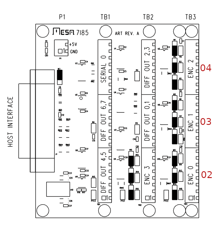
On the 7i85S I get a count on the connectors of TB3 (ENC0, ENC1, ENC2) and I see they corespond to hm2_7i96.0.encoder.02, hm2_7i96.0.encoder.03 and hm2_7i96.0.encoder.04.
No sign of life on TB2 Enc3 (I've not tested the encoder on the 7i96 so far).
Is that due to the limited capacity of the FPGA on the 7i96?
2.
Does it make sense to configure linuxcnc to use the encoder feedback for a PID regulator?
I've read somewhere that I could just use the encoder feedback to show the f-error somehow but don't remember wehere that was :-/
Can the encoder position be somehow displayed on the Axis GUI?
3.
There is a connector serial on the 7i96, is that a SmartSerial for wireing Smart Serial cards to it?
The same question applies to the serial connector on the 7i85S.
4.
The differential outputs of the 7i85S can be used as normal outputs, right?
Does that need any special config in order to use these outputs?
5.
What card is the best choice to get more inputs (and maybe outputs) that can be used with 24VDC?
I have a setup that consists of a Mesa 7i96 and a 7i85S
and a Yaskawa Sigma II 30W Servodriver + Motor with incremental encoder.
I installed a Debian 10 Buster + LinuxCNC 2.9 from the sources. Flashed the right Bitfile and created a basic config using the 7i96 tool .
I configured the Servo that it runs in Position mode and takes Step/Dir signals from the 7i96 and wired the encoder outputs to the 7i85S.
So far I can drive the motor and I see the encoder feedback in the HAL Configuration, but I have many questions:
1.
How are the encoders supposed to be numbered on the two Mesa boards?
At the moment it seems a little weird.
I can see in the HAL components that there are 5 encoers listet:
hm2_7i96.0.encoder.00
hm2_7i96.0.encoder.01
hm2_7i96.0.encoder.02
hm2_7i96.0.encoder.03
hm2_7i96.0.encoder.04
On the 7i85S I get a count on the connectors of TB3 (ENC0, ENC1, ENC2) and I see they corespond to hm2_7i96.0.encoder.02, hm2_7i96.0.encoder.03 and hm2_7i96.0.encoder.04.
No sign of life on TB2 Enc3 (I've not tested the encoder on the 7i96 so far).
Is that due to the limited capacity of the FPGA on the 7i96?
2.
Does it make sense to configure linuxcnc to use the encoder feedback for a PID regulator?
I've read somewhere that I could just use the encoder feedback to show the f-error somehow but don't remember wehere that was :-/
Can the encoder position be somehow displayed on the Axis GUI?
3.
There is a connector serial on the 7i96, is that a SmartSerial for wireing Smart Serial cards to it?
The same question applies to the serial connector on the 7i85S.
4.
The differential outputs of the 7i85S can be used as normal outputs, right?
Does that need any special config in order to use these outputs?
5.
What card is the best choice to get more inputs (and maybe outputs) that can be used with 24VDC?
Attachments:
Please Log in or Create an account to join the conversation.
- Becksvill
- Offline
- Elite Member
-

Less
More
- Posts: 209
- Thank you received: 106
14 May 2020 07:14 #167703
by Becksvill
Replied by Becksvill on topic 7i96E + 7i85S + AC Servo - encoder feedback
Hi just a quick reply for now.
I am not a expert but I have just spent most of the last 4 days doing exactly what you want to do. I currently don't have a 7i85 or 7i89 card for the encoders so I have been using my 7i76 spindle encoder inputs instead but it is exactly the same idea I think.
I have been trawling the forum here and googling for days and have it mostly working now,
From how I understand it basicly there are two ways to do this
you can run in open loop but have the final encoder position displayed in axis DRO as you say. but with this method there are no actual Pid loops inside linuxcnc (thats not quite correct - there is one that makes the step gen pulses.. but you can ignore that one for now)
both ways are not that hard to set up.
the other way is to connect up encoder to a couple more Hal connections and have a PID loop in linuxcnc that has final say once the servo drive position loop has moved to where it needs to go. From what I understand this PID loop should only have a little Integral value and most of the tuning is still done in the servo drive.
My chinese servo drives are a almost exact copy of Sigma 1 or 2 servo drives and i have been reading the manuals for the past 3 days lol
I have changed pretty much everything possible on those drives just to see what did what. If you want help I am happy as to help.
once again I am not a expert so once the experts chime in here they will probably have better ideas. But I have been working this out all this week.
here is my build thread. if you are interested
forum.linuxcnc.org/show-your-stuff/39021...ives-build-thread-nz
Regards
Andrew
Please Log in or Create an account to join the conversation.
- Becksvill
- Offline
- Elite Member
-
Less
More
- Posts: 209
- Thank you received: 106
14 May 2020 07:20 #167705
by Becksvill
Replied by Becksvill on topic 7i96E + 7i85S + AC Servo - encoder feedback
missed some things and re read your post.
I think the best mesa card for more 24v IO pins is the 7i84 I am going to get a couple more of those shortly for my machines as I am running out of 24v digital IO
the good thing about the 7i84 is that it is connected to the rest of the cards with a ethernet cable and that means you can put it in the front of your machine, if you want for the control panel buttons. that really simplifies matters on big machines like my one. (5ton beastie)
the rest of your questions i don't know sorry. that is a good question for the more experienced guys on here
regards
Andrew
Please Log in or Create an account to join the conversation.
- Bouni
- Offline
- New Member
-
Less
More
- Posts: 14
- Thank you received: 2
14 May 2020 11:22 #167723
by Bouni
Replied by Bouni on topic 7i96E + 7i85S + AC Servo - encoder feedback
Hi Andrew,
thanks a lot for your detailed answers!
I will read the thread you've linked, maybe that answers my questions or at least brings me closer to my goals!
thanks a lot for your detailed answers!
I will read the thread you've linked, maybe that answers my questions or at least brings me closer to my goals!
Please Log in or Create an account to join the conversation.
- PCW
-

- Offline
- Moderator
-

Less
More
- Posts: 17996
- Thank you received: 5283
14 May 2020 13:25 #167742
by PCW
Replied by PCW on topic 7i96E + 7i85S + AC Servo - encoder feedback
What does
mesaflash --device 7i96 --readhmid
or
mesaflash --device 7i96 --addr 10.10.10.10 --readhmid
report
The 7i96_7i85sd.bit at mesanet.com in 7i96.zip
md5sum:
e3959c51451294c21a751a65f024a36f 7i96_7i85sd.bit
should map encoders:
4 7I96
5 7i96 alias
0 7i85 enc0
1 7i85 enc1
2 7i85 enc2
3 7i85 enc3
mesaflash --device 7i96 --readhmid
or
mesaflash --device 7i96 --addr 10.10.10.10 --readhmid
report
The 7i96_7i85sd.bit at mesanet.com in 7i96.zip
md5sum:
e3959c51451294c21a751a65f024a36f 7i96_7i85sd.bit
should map encoders:
4 7I96
5 7i96 alias
0 7i85 enc0
1 7i85 enc1
2 7i85 enc2
3 7i85 enc3
Please Log in or Create an account to join the conversation.
- Bouni
- Offline
- New Member
-
Less
More
- Posts: 14
- Thank you received: 2
14 May 2020 13:30 #167743
by Bouni
Replied by Bouni on topic 7i96E + 7i85S + AC Servo - encoder feedback
I'll check as soon as I get home to my setup and let you know!
Please Log in or Create an account to join the conversation.
- Bouni
- Offline
- New Member
-
Less
More
- Posts: 14
- Thank you received: 2
17 May 2020 10:28 #168038
by Bouni
Replied by Bouni on topic 7i96E + 7i85S + AC Servo - encoder feedback
Here's the output of mesaflash:
Unfortunately I flashed the bitfile several months ago and do not have the bit file around anymore.
I guess there is no way of getting a checksum of the loaded bitfile?
The next thing that's very strange is that I've ordered a 7i85S at EUSurplus an they confirmed that type on the order confirmation, but on my card the silkscreen says just 7I85. On the Mesanet store the 7i85 and 7i85S show the exactly same image.
Is there a hardware difference between these two boards and if so, how can I figure out which one I got?
Maybe the problem is the wrong board for the bitfile!?
mesaflash --device 7i96 --readhmid
Configuration Name: HOSTMOT2

General configuration information:

  BoardName : MESA7I96
  FPGA Size: 9 KGates
  FPGA Pins: 144
  Number of IO Ports: 3
  Width of one I/O port: 17
  Clock Low frequency: 100.0000 MHz
  Clock High frequency: 200.0000 MHz
  IDROM Type: 3
  Instance Stride 0: 4
  Instance Stride 1: 64
  Register Stride 0: 256
  Register Stride 1: 256

Modules in configuration:

  Module: DPLL
  There are 1 of DPLL in configuration
  Version: 0
  Registers: 7
  BaseAddress: 7000
  ClockFrequency: 100.000 MHz
  Register Stride: 256 bytes
  Instance Stride: 4 bytes

  Module: WatchDog
  There are 1 of WatchDog in configuration
  Version: 0
  Registers: 3
  BaseAddress: 0C00
  ClockFrequency: 100.000 MHz
  Register Stride: 256 bytes
  Instance Stride: 4 bytes

  Module: IOPort
  There are 3 of IOPort in configuration
  Version: 0
  Registers: 5
  BaseAddress: 1000
  ClockFrequency: 100.000 MHz
  Register Stride: 256 bytes
  Instance Stride: 4 bytes

  Module: StepGen
  There are 8 of StepGen in configuration
  Version: 2
  Registers: 10
  BaseAddress: 2000
  ClockFrequency: 100.000 MHz
  Register Stride: 256 bytes
  Instance Stride: 4 bytes

  Module: MuxedQCount
  There are 6 of MuxedQCount in configuration
  Version: 3
  Registers: 5
  BaseAddress: 3600
  ClockFrequency: 100.000 MHz
  Register Stride: 256 bytes
  Instance Stride: 4 bytes

  Module: MuxedQCountSel
  There are 1 of MuxedQCountSel in configuration
  Version: 0
  Registers: 0
  BaseAddress: 0000
  ClockFrequency: 100.000 MHz
  Register Stride: 256 bytes
  Instance Stride: 4 bytes

  Module: SSerial
  There are 1 of SSerial in configuration
  Version: 0
  Registers: 6
  BaseAddress: 5B00
  ClockFrequency: 100.000 MHz
  Register Stride: 256 bytes
  Instance Stride: 64 bytes

  Module: SSR
  There are 1 of SSR in configuration
  Version: 0
  Registers: 2
  BaseAddress: 7D00
  ClockFrequency: 100.000 MHz
  Register Stride: 256 bytes
  Instance Stride: 4 bytes

  Module: LED
  There are 1 of LED in configuration
  Version: 0
  Registers: 1
  BaseAddress: 0200
  ClockFrequency: 100.000 MHz
  Register Stride: 256 bytes
  Instance Stride: 4 bytes

Configuration pin-out:

IO Connections for TB3
Pin#  I/O   Pri. func    Sec. func       Chan      Pin func        Pin Dir

 1      0   IOPort       None
14      1   IOPort       None
 2      2   IOPort       None
15      3   IOPort       None
 3      4   IOPort       None
16      5   IOPort       None
 4      6   IOPort       None
17      7   IOPort       None
 5      8   IOPort       None
 6      9   IOPort       None
 7     10   IOPort       None
 8     11   IOPort       SSR              0        Out-00          (Out)
 9     12   IOPort       SSR              0        Out-01          (Out)
10     13   IOPort       SSR              0        Out-02          (Out)
11     14   IOPort       SSR              0        Out-03          (Out)
12     15   IOPort       SSR              0        Out-04          (Out)
13     16   IOPort       SSR              0        Out-05          (Out)

IO Connections for TB1/TB2
Pin#  I/O   Pri. func    Sec. func       Chan      Pin func        Pin Dir

 1     17   IOPort       StepGen          0        Step/Table1     (Out)
14     18   IOPort       StepGen          0        Dir/Table2      (Out)
 2     19   IOPort       StepGen          1        Step/Table1     (Out)
15     20   IOPort       StepGen          1        Dir/Table2      (Out)
 3     21   IOPort       StepGen          2        Step/Table1     (Out)
16     22   IOPort       StepGen          2        Dir/Table2      (Out)
 4     23   IOPort       StepGen          3        Step/Table1     (Out)
17     24   IOPort       StepGen          3        Dir/Table2      (Out)
 5     25   IOPort       StepGen          4        Step/Table1     (Out)
 6     26   IOPort       StepGen          4        Dir/Table2      (Out)
 7     27   IOPort       MuxedQCount      0        MuxQ-IDX        (In)
 8     28   IOPort       MuxedQCount      0        MuxQ-B          (In)
 9     29   IOPort       MuxedQCount      0        MuxQ-A          (In)
10     30   IOPort       SSerial          0        RXData0         (In)
11     31   IOPort       SSerial          0        TXData0         (Out)
12     32   IOPort       SSerial          0        TXEn0           (Out)
13     33   IOPort       SSR              0        AC Ref          (Out)

IO Connections for P1
Pin#  I/O   Pri. func    Sec. func       Chan      Pin func        Pin Dir

 1     34   IOPort       SSerial          0        RXData1         (In)
14     35   IOPort       SSerial          0        TXData1         (Out)
 2     36   IOPort       None
15     37   IOPort       None
 3     38   IOPort       StepGen          7        Step/Table1     (Out)
16     39   IOPort       StepGen          7        Dir/Table2      (Out)
 4     40   IOPort       StepGen          6        Step/Table1     (Out)
17     41   IOPort       StepGen          6        Dir/Table2      (Out)
 5     42   IOPort       StepGen          5        Step/Table1     (Out)
 6     43   IOPort       StepGen          5        Dir/Table2      (Out)
 7     44   IOPort       MuxedQCountSel   2        MuxSel0         (Out)
 8     45   IOPort       MuxedQCount      1        MuxQ-A          (In)
 9     46   IOPort       MuxedQCount      1        MuxQ-B          (In)
10     47   IOPort       MuxedQCount      1        MuxQ-IDX        (In)
11     48   IOPort       MuxedQCount      2        MuxQ-A          (In)
12     49   IOPort       MuxedQCount      2        MuxQ-B          (In)
13     50   IOPort       MuxedQCount      2        MuxQ-IDX        (In)
Unfortunately I flashed the bitfile several months ago and do not have the bit file around anymore.
I guess there is no way of getting a checksum of the loaded bitfile?
The next thing that's very strange is that I've ordered a 7i85S at EUSurplus an they confirmed that type on the order confirmation, but on my card the silkscreen says just 7I85. On the Mesanet store the 7i85 and 7i85S show the exactly same image.
Is there a hardware difference between these two boards and if so, how can I figure out which one I got?
Maybe the problem is the wrong board for the bitfile!?
Please Log in or Create an account to join the conversation.
- PCW
-
- Offline
- Moderator
-
Less
More
- Posts: 17996
- Thank you received: 5283
17 May 2020 14:39 - 17 May 2020 14:39 #168066
by PCW
Replied by PCW on topic 7i96E + 7i85S + AC Servo - encoder feedback
The 7I85 and 7I85S have the same PCB but have different assembly options
The back of the card will have a lot label that has the actual part #
You can also tell from the components, on a 7I85, there will be a
120 Ohm 1206 resistor by the 7I85S Stepgen output locations. these will be
empty on a 7I85S. You are running 7I85S firmware and the encoder order is
as expected (you will need to enable 6 encoders in your hal file to make the last
7I85S encoder available)
Last edit: 17 May 2020 14:39 by PCW.
Please Log in or Create an account to join the conversation.
- Bouni
- Offline
- New Member
-
Less
More
- Posts: 14
- Thank you received: 2
18 May 2020 12:49 #168145
by Bouni
Replied by Bouni on topic 7i96E + 7i85S + AC Servo - encoder feedback
I just checked and the resistors are empty and the label on the back side says its a 7i85S.
I have currently 5 encoders configured. Can you tell me why I need to configure 6?
There is one on the 7i96 and 4 on the 7i85S !?
What would be the correct number for this setup, 4 Stepgens, 2 SmartSerial and 6 encoders?
I have currently 5 encoders configured. Can you tell me why I need to configure 6?
There is one on the 7i96 and 4 on the 7i85S !?
What would be the correct number for this setup, 4 Stepgens, 2 SmartSerial and 6 encoders?
Please Log in or Create an account to join the conversation.
- PCW
-
- Offline
- Moderator
-
Less
More
- Posts: 17996
- Thank you received: 5283
18 May 2020 13:33 - 18 May 2020 13:33 #168149
by PCW
Replied by PCW on topic 7i96E + 7i85S + AC Servo - encoder feedback
The 7I85/7I85S uses multiplexed encoders, The LinuxCNC driver can support multiplexed
encoders or non-multiplexed encoders but not both at the same time. This means that the
7I96 non-multiplexed encoder connection must use multiplexed hardware. What this means
practically is that the 7I96 will have an aliased encoder:
7I96 ENC HAL ENC 0
7I96 ENC HAL ENC1 (alias of ENC 0)
7I85S ENC 0 HAL ENC 2
7I85S ENC 1 HAL ENC 3
7I85S ENC 2 HAL ENC 4
7I85S ENC 3 HAL ENC 5
The correct setup number would be to enable as many modules as you need, the maximum numbers
of modules enabled would be 8 stepgens, 6 encoders, 2 sserials
Last edit: 18 May 2020 13:33 by PCW.
Please Log in or Create an account to join the conversation.
Time to create page: 0.124 seconds