- Configuring LinuxCNC
- Basic Configuration
- Mesa 7i76E and NKS E3000C Spindle Wiring Configuration Help
Mesa 7i76E and NKS E3000C Spindle Wiring Configuration Help
- umfan110
-
 Topic Author
- Offline
- Junior Member
-

Less
More
- Posts: 32
- Thank you received: 2
25 Sep 2022 18:38 - 25 Sep 2022 18:44 #252723
by umfan110
Mesa 7i76E and NKS E3000C Spindle Wiring Configuration Help was created by umfan110
I was wondering if someone could provide some input on my wiring between my NKS E3000C Spindle Controller and my Mesa 7i76E Card. Looking at the manual for the 7i76E there are 8 pins on TB4. From what I understand there is a digital pot within the mesa card that can provide a variable voltage to the controller (Pins 1,2 and 3). Outside of that there is Spindle enable and Spindle Dir (pin 5,6 and 7,8).
Looking at the E3000C Manual there is D-Sub 2 row 25 pin I/O interface on the front of the controller that I tapped into. It all looks pretty promising and I think should work.
The pins I targeted on the E3000C are as follows:
Pin 11: +10DCV Power Output
Pin 23: VR 0-10VDC Motor Speed Control Signal, able to read 0-10 volts.
Pin 10: GRD Internal GRD
Pin 2: DIR_IN Rotation directional signal off meaning FWD and on reverse
Pin 14: Start Rotate command signal
I wired between the two as follows:
NKS E3000C TB4
11 3,6,8 (10+ VDC to Spindle DIR +, Spindle Enable +, Spindle +)
23 2 (POT signal from mesa card to pin 23 Motor Speed Control signal)
10 1 (GRD from NKS to Spinde - TB4)
2 7 (DIR pin from NKS to Spindle DIR - on TB4)
14 5 (Start Rotate signal form NKS to Spindle ENA- on TB4)
Attached is a diagram of my wiring config.
When testing this configuration I see the speed values updating but it seems that the spindle enable signal and DIR signals are not coming through. When I look at HAL I see the pins acting accordingly. I am not sure where I am going wrong. Could it be a grounding issue ? The controller and power supply are on two different circuits. Should I connect the grounds of the power supply to the mesa card to the ground
of the E3000C controller. Electrical is not my specialty.
Reading the manual of the E3000C I dont see any other pins that stand out to me and reading Setting Auto Mode (page 22) It says that one needs Pins 2, 14, and 23.
I am assuming pin 14 on NKS (Start) is the same as enable on TB4. Is there something I could be missing? I feel like I am close.
Thanks!
Last edit: 25 Sep 2022 18:44 by umfan110. Reason: Formatting Issues
Please Log in or Create an account to join the conversation.
- PCW
-

- Away
- Moderator
-

Less
More
- Posts: 17996
- Thank you received: 5283
26 Sep 2022 22:14 #252806
by PCW
Replied by PCW on topic Mesa 7i76E and NKS E3000C Spindle Wiring Configuration Help
I would check that the drives enable and direction inputs work as you expect
(does connecting them to +10V actives them?)
(does connecting them to +10V actives them?)
Please Log in or Create an account to join the conversation.
- umfan110
-
Topic Author
- Offline
- Junior Member
-
Less
More
- Posts: 32
- Thank you received: 2
29 Sep 2022 22:45 #253062
by umfan110
Replied by umfan110 on topic Mesa 7i76E and NKS E3000C Spindle Wiring Configuration Help
Working on that now, will report back.
I do see two pins of interest.
Pin 1: COM - 24VDC power source for external control inputs (0-24v)
Pin 18: GND - External power source GND
Would I connect those two pins to the same power supply as the 7i76e ?
Then disconnect ENA + and DIR+ entirely from the mesa card?
Im worried to just jump right in and test that, I dont want to short out the 7i76e.
Please Log in or Create an account to join the conversation.
- PCW
-
- Away
- Moderator
-
Less
More
- Posts: 17996
- Thank you received: 5283
29 Sep 2022 23:13 #253065
by PCW
Replied by PCW on topic Mesa 7i76E and NKS E3000C Spindle Wiring Configuration Help
You always need ENA+ and ENA- (and DIR+ and DIR-)
because these are switch outputs
(The + and - pins are connected together when on)
Do you have a link to the drive manual?
because these are switch outputs
(The + and - pins are connected together when on)
Do you have a link to the drive manual?
Please Log in or Create an account to join the conversation.
- umfan110
-
Topic Author
- Offline
- Junior Member
-
Less
More
- Posts: 32
- Thank you received: 2
30 Sep 2022 17:47 #253116
by umfan110
Replied by umfan110 on topic Mesa 7i76E and NKS E3000C Spindle Wiring Configuration Help
Yeah here is the manual.
www.nsk-nakanishi.co.jp/industrial-eng/d...al/sale/e3000_en.pdf
Page 13 is where all the pin outs are listed.
www.nsk-nakanishi.co.jp/industrial-eng/d...al/sale/e3000_en.pdf
Page 13 is where all the pin outs are listed.
Please Log in or Create an account to join the conversation.
- PCW
-
- Away
- Moderator
-
Less
More
- Posts: 17996
- Thank you received: 5283
30 Sep 2022 17:58 #253117
by PCW
Replied by PCW on topic Mesa 7i76E and NKS E3000C Spindle Wiring Configuration Help
I would say:
+24V --> Drive 1
7I76E DIR+ --> Drive 2
7I76E DIR- --> 24V GND
7I76E ENA+ --> Drive 14
7I76E ENA- --> 24V GND
+24V --> Drive 1
7I76E DIR+ --> Drive 2
7I76E DIR- --> 24V GND
7I76E ENA+ --> Drive 14
7I76E ENA- --> 24V GND
The following user(s) said Thank You: umfan110
Please Log in or Create an account to join the conversation.
- umfan110
-
Topic Author
- Offline
- Junior Member
-
Less
More
- Posts: 32
- Thank you received: 2
30 Sep 2022 22:07 #253126
by umfan110
Replied by umfan110 on topic Mesa 7i76E and NKS E3000C Spindle Wiring Configuration Help
Ok Ill give that a try. Thanks for the insight ! At the end of all this Ill create some official documentation !
Please Log in or Create an account to join the conversation.
- umfan110
-
Topic Author
- Offline
- Junior Member
-
Less
More
- Posts: 32
- Thank you received: 2
30 Sep 2022 22:30 #253129
by umfan110
Replied by umfan110 on topic Mesa 7i76E and NKS E3000C Spindle Wiring Configuration Help
That worked ! Thanks again Ill post a PDF of the config later tonight !
Please Log in or Create an account to join the conversation.
- cakeslob
- Offline
- Platinum Member
-

Less
More
- Posts: 926
- Thank you received: 278
31 Oct 2022 03:35 #255539
by cakeslob
Hey PCW, I have this same E3000c driver with a 7i76, so I have this same issue. I have all the driver inputs connected to regular outputs on the 7i76, with 24v GND --> Drive 1
Will I still be able to use the other pins if I change to +24?
I am also having issues with the wiring of the encoder index,( and the analog feedback)
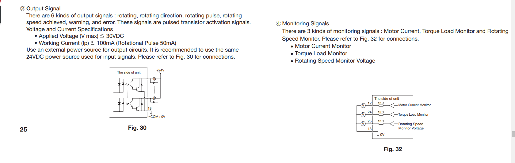
Any suggestions on where/how I can wire this (fig 30) to a 7i76?
Its 24v so Im having a hard time wiring it up and getting the correct reading.
Replied by cakeslob on topic Mesa 7i76E and NKS E3000C Spindle Wiring Configuration Help
I would say:
+24V --> Drive 1
7I76E DIR+ --> Drive 2
7I76E DIR- --> 24V GND
7I76E ENA+ --> Drive 14
7I76E ENA- --> 24V GND
Hey PCW, I have this same E3000c driver with a 7i76, so I have this same issue. I have all the driver inputs connected to regular outputs on the 7i76, with 24v GND --> Drive 1
Will I still be able to use the other pins if I change to +24?
I am also having issues with the wiring of the encoder index,( and the analog feedback)
Any suggestions on where/how I can wire this (fig 30) to a 7i76?
Its 24v so Im having a hard time wiring it up and getting the correct reading.
Attachments:
Please Log in or Create an account to join the conversation.
- PCW
-
- Away
- Moderator
-
Less
More
- Posts: 17996
- Thank you received: 5283
31 Oct 2022 14:16 #255575
by PCW
Replied by PCW on topic Mesa 7i76E and NKS E3000C Spindle Wiring Configuration Help
Yes, you can use the ENA and DIR OPTO outputs if you change
the drives input common to +24V (if that's what you meant)
Are you saying that the index output is an open collector output
like that shown in Fig. 30? It should be possible to use that outpu
with the encoder index input if that input is jumpered for TTL mode.
the drives input common to +24V (if that's what you meant)
Are you saying that the index output is an open collector output
like that shown in Fig. 30? It should be possible to use that outpu
with the encoder index input if that input is jumpered for TTL mode.
Please Log in or Create an account to join the conversation.
- Configuring LinuxCNC
- Basic Configuration
- Mesa 7i76E and NKS E3000C Spindle Wiring Configuration Help
Time to create page: 0.125 seconds