"pwm/dir" (Out1) switches for spindle CCW
- juergen-home
- Offline
- Senior Member
-

Less
More
- Posts: 44
- Thank you received: 15
11 Aug 2025 12:05 - 11 Aug 2025 12:18 #333214
by juergen-home
"pwm/dir" (Out1) switches for spindle CCW was created by juergen-home
Hi there
A question about my configuration:
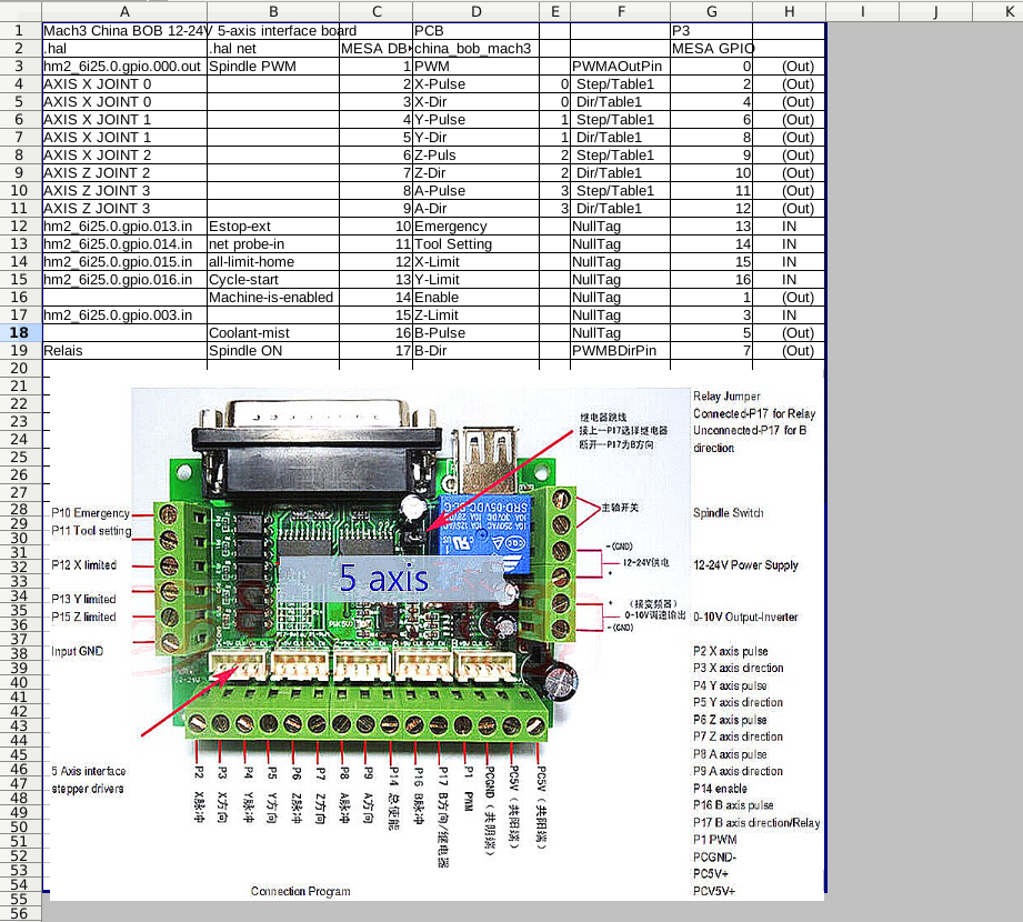
1. I have a HF milling spindle which needs only to turns clockwise. The PWM canal (Out0) works fine. My config for "pwm/dir" (Out1) is set to a relay output (P17/"GPIO7"). The relay should be on when CW is commanded but here it is on when CCW is commanded. How config it so that the relay switch on when CW is commanded?
Mesa 6i25 with homemade pin file
China BOB Mach3
Linuxcnc 2.8.4-1gb7824717b
A question about my configuration:
1. I have a HF milling spindle which needs only to turns clockwise. The PWM canal (Out0) works fine. My config for "pwm/dir" (Out1) is set to a relay output (P17/"GPIO7"). The relay should be on when CW is commanded but here it is on when CCW is commanded. How config it so that the relay switch on when CW is commanded?
Mesa 6i25 with homemade pin file
China BOB Mach3
Linuxcnc 2.8.4-1gb7824717b
# Erstellt von PNCconf am Mon May  1 19:24:03 2023
# Verwendete LinuxCNC version:  Master (2.9)
# Änderungen an dieser Datei werden beim nächsten
# wird überschrieben sobald Sie PNCconf erneut ausführen

#2.8.4

loadrt [KINS]KINEMATICS
loadrt [EMCMOT]EMCMOT servo_period_nsec=[EMCMOT]SERVO_PERIOD num_joints=[KINS]JOINTS
loadrt hostmot2
loadrt hm2_pci config="num_encoders=5 num_pwmgens=1 num_stepgens=4 sserial_port_0=0xxxxxxx"
#loadrt hm2_pci config="num_encoders=5 num_pwmgens=1 num_stepgens=3 sserial_port_0=0xxxxxxx"

# firmware=hm2/Discovered:6i25/~/mesa0_discovered.xml.BIT
setp    hm2_6i25.0.pwmgen.pwm_frequency 1000
setp    hm2_6i25.0.pwmgen.pdm_frequency 6000000
setp    hm2_6i25.0.watchdog.timeout_ns 5000000
loadrt pid names=pid.x,pid.y,pid.z,pid.a,pid.s

# lut5: look up table für all-limit-home (because of problem with linit stop detection by other axes when homing)
loadrt lut5 names=lut_homing
addf lut_homing servo-thread
setp lut_homing.function 0x10000
net all-limit-home => lut_homing.in-4
net all-limit <= lut_homing.out
net homing-x <= joint.0.homing => lut_homing.in-0
net homing-y <= joint.1.homing => lut_homing.in-1
net homing-z <= joint.2.homing => lut_homing.in-2
##setp lut_homing.in-3  0
##net homing-a <= joint.2.homing => lut_homing.in-3


addf hm2_6i25.0.read          servo-thread
addf motion-command-handler   servo-thread
addf motion-controller        servo-thread
addf pid.x.do-pid-calcs       servo-thread
addf pid.y.do-pid-calcs       servo-thread
addf pid.z.do-pid-calcs       servo-thread
addf pid.a.do-pid-calcs       servo-thread
addf pid.s.do-pid-calcs       servo-thread
addf hm2_6i25.0.write         servo-thread
setp hm2_6i25.0.dpll.01.timer-us -50
setp hm2_6i25.0.stepgen.timer-number 1

# extern signal input

# --- MACHINE-IS-ENABLED ---
#gpio.001 MESA DB25 PIN PIN 14
setp hm2_6i25.0.gpio.001.is_output true
net machine-is-enabled  =>     hm2_6i25.0.gpio.001.out

# --- COOLANT-MIST ---
#gpio.005 MESA DB25 PIN PIN 16
setp hm2_6i25.0.gpio.005.is_output true
#net coolant-mist  =>     hm2_6i25.0.gpio.005.out

# externe signal output

# --- ESTOP-EXT ---
#gpio.013 MESA DB25 PIN PIN 10
# .in_not for NC / .in for NO Limit Switch
net estop-ext     <=  hm2_6i25.0.gpio.013.in_not
#net estop-ext     <=  hm2_6i25.0.gpio.013.in

# --- PROBE-IN ---
# -wird in Probe_postgui.hal verwendet / definiert -
#gpio.014 MESA DB25 PIN PIN 11
#net probe-in     <=  hm2_6i25.0.gpio.014.in

# --- ALL-LIMIT-HOME ---
# gpio.015 MESA DB25 PIN PIN 12
# .in_not for NO / .in for NC Limit Switch
net all-limit-home     <=  hm2_6i25.0.gpio.015.in_not
#net all-limit-home     <=  hm2_6i25.0.gpio.015.in

# --- CYCLE-START ---
#gpio.016 MESA DB25 PIN PIN 13
#net cycle-start     <=  hm2_6i25.0.gpio.016.in

#*******************
#  AXIS X JOINT 0
#*******************

setp   pid.x.Pgain     [JOINT_0]P
setp   pid.x.Igain     [JOINT_0]I
setp   pid.x.Dgain     [JOINT_0]D
setp   pid.x.bias      [JOINT_0]BIAS
setp   pid.x.FF0       [JOINT_0]FF0
setp   pid.x.FF1       [JOINT_0]FF1
setp   pid.x.FF2       [JOINT_0]FF2
setp   pid.x.deadband  [JOINT_0]DEADBAND
setp   pid.x.maxoutput [JOINT_0]MAX_OUTPUT
setp   pid.x.error-previous-target true
# This setting is to limit bogus stepgen
# velocity corrections caused by position
# feedback sample time jitter.
setp   pid.x.maxerror 0.012700

#net x-index-enable  =>  pid.x.index-enable
#net x-enable        =>  pid.x.enable
#net x-pos-cmd       =>  pid.x.command
#net x-pos-fb        =>  pid.x.feedback
#net x-output        <=  pid.x.output

# Step-Gen Signal/Setup

setp   hm2_6i25.0.stepgen.00.dirsetup        [JOINT_0]DIRSETUP
setp   hm2_6i25.0.stepgen.00.dirhold         [JOINT_0]DIRHOLD
setp   hm2_6i25.0.stepgen.00.steplen         [JOINT_0]STEPLEN
setp   hm2_6i25.0.stepgen.00.stepspace       [JOINT_0]STEPSPACE
setp   hm2_6i25.0.stepgen.00.position-scale  [JOINT_0]STEP_SCALE
setp   hm2_6i25.0.stepgen.00.step_type        0
#setp   hm2_6i25.0.stepgen.00.control-type     1
setp   hm2_6i25.0.stepgen.00.control-type     0
setp   hm2_6i25.0.stepgen.00.maxaccel         [JOINT_0]STEPGEN_MAXACCEL
setp   hm2_6i25.0.stepgen.00.maxvel           [JOINT_0]STEPGEN_MAXVEL

#-closed loop umgehen (von sim-maschine)
net x-pos-fb     joint.0.motor-pos-fb   <=  hm2_6i25.0.stepgen.00.position-fb
net x-pos-cmd    joint.0.motor-pos-cmd  =>  hm2_6i25.0.stepgen.00.position-cmd
net x-enable     joint.0.amp-enable-out =>  hm2_6i25.0.stepgen.00.enable


# ---Closed-Loop Schrittmotor-Signale---

#net x-pos-cmd    <= joint.0.motor-pos-cmd
#net x-vel-cmd    <= joint.0.vel-cmd
#net x-output     => hm2_6i25.0.stepgen.00.velocity-cmd
#net x-pos-fb     <= hm2_6i25.0.stepgen.00.position-fb
#net x-pos-fb     => joint.0.motor-pos-fb
#net x-enable     <= joint.0.amp-enable-out
#net x-enable     => hm2_6i25.0.stepgen.00.enable

# ---Einrichtung Referenzfahrt / Signale der Endschalter---

net all-limit-home     =>  joint.0.home-sw-in
net all-limit    =>  joint.0.neg-lim-sw-in
net all-limit     =>  joint.0.pos-lim-sw-in


#*******************
#  AXIS Y JOINT 1
#*******************

setp   pid.y.Pgain     [JOINT_1]P
setp   pid.y.Igain     [JOINT_1]I
setp   pid.y.Dgain     [JOINT_1]D
setp   pid.y.bias      [JOINT_1]BIAS
setp   pid.y.FF0       [JOINT_1]FF0
setp   pid.y.FF1       [JOINT_1]FF1
setp   pid.y.FF2       [JOINT_1]FF2
setp   pid.y.deadband  [JOINT_1]DEADBAND
setp   pid.y.maxoutput [JOINT_1]MAX_OUTPUT
setp   pid.y.error-previous-target true
# This setting is to limit bogus stepgen
# velocity corrections caused by position
# feedback sample time jitter.
setp   pid.y.maxerror 0.012700

#net y-index-enable  =>  pid.y.index-enable
#net y-enable        =>  pid.y.enable
#net y-pos-cmd       =>  pid.y.command
#net y-pos-fb        =>  pid.y.feedback
#net y-output        <=  pid.y.output

# Schritt-Gen Signale/Setup
#setp hm2_6i25.0.gpio.003.invert_output true

setp   hm2_6i25.0.stepgen.01.dirsetup        [JOINT_1]DIRSETUP
setp   hm2_6i25.0.stepgen.01.dirhold         [JOINT_1]DIRHOLD
setp   hm2_6i25.0.stepgen.01.steplen         [JOINT_1]STEPLEN
setp   hm2_6i25.0.stepgen.01.stepspace       [JOINT_1]STEPSPACE
setp   hm2_6i25.0.stepgen.01.position-scale  [JOINT_1]STEP_SCALE
setp   hm2_6i25.0.stepgen.01.step_type        0
#setp   hm2_6i25.0.stepgen.01.control-type     1
setp   hm2_6i25.0.stepgen.01.control-type     0
setp   hm2_6i25.0.stepgen.01.maxaccel         [JOINT_1]STEPGEN_MAXACCEL
setp   hm2_6i25.0.stepgen.01.maxvel           [JOINT_1]STEPGEN_MAXVEL

#-closed loop umgehen (von sim-maschine)
net y-pos-fb     joint.1.motor-pos-fb   <=  hm2_6i25.0.stepgen.01.position-fb
net y-pos-cmd    joint.1.motor-pos-cmd  =>  hm2_6i25.0.stepgen.01.position-cmd
net y-enable     joint.1.amp-enable-out =>  hm2_6i25.0.stepgen.01.enable


# ---Closed-Loop Schrittmotor-Signale---

#net y-pos-cmd    <= joint.1.motor-pos-cmd
#net y-vel-cmd    <= joint.1.vel-cmd
#net y-output     => hm2_6i25.0.stepgen.01.velocity-cmd
#net y-pos-fb     <= hm2_6i25.0.stepgen.01.position-fb
#net y-pos-fb     => joint.1.motor-pos-fb
#net y-enable     <= joint.1.amp-enable-out
#net y-enable     => hm2_6i25.0.stepgen.01.enable

# ---Einrichtung Referenzfahrt / Signale der Endschalter---

net all-limit-home     =>  joint.1.home-sw-in
net all-limit     =>  joint.1.neg-lim-sw-in
net all-limit     =>  joint.1.pos-lim-sw-in

#*******************
#  AXIS Z JOINT 2
#*******************

setp   pid.z.Pgain     [JOINT_2]P
setp   pid.z.Igain     [JOINT_2]I
setp   pid.z.Dgain     [JOINT_2]D
setp   pid.z.bias      [JOINT_2]BIAS
setp   pid.z.FF0       [JOINT_2]FF0
setp   pid.z.FF1       [JOINT_2]FF1
setp   pid.z.FF2       [JOINT_2]FF2
setp   pid.z.deadband  [JOINT_2]DEADBAND
setp   pid.z.maxoutput [JOINT_2]MAX_OUTPUT
setp   pid.z.error-previous-target true
# This setting is to limit bogus stepgen
# velocity corrections caused by position
# feedback sample time jitter.
setp   pid.z.maxerror 0.012700

#net z-index-enable  =>  pid.z.index-enable
#net z-enable        =>  pid.z.enable
#net z-pos-cmd       =>  pid.z.command
#net z-pos-fb        =>  pid.z.feedback
#net z-output        <=  pid.z.output

# Schritt-Gen Signale/Setup
setp hm2_6i25.0.gpio.003.invert_output true

setp   hm2_6i25.0.stepgen.02.dirsetup        [JOINT_2]DIRSETUP
setp   hm2_6i25.0.stepgen.02.dirhold         [JOINT_2]DIRHOLD
setp   hm2_6i25.0.stepgen.02.steplen         [JOINT_2]STEPLEN
setp   hm2_6i25.0.stepgen.02.stepspace       [JOINT_2]STEPSPACE
setp   hm2_6i25.0.stepgen.02.position-scale  [JOINT_2]STEP_SCALE
setp   hm2_6i25.0.stepgen.02.step_type        0
#setp   hm2_6i25.0.stepgen.02.control-type     1
setp   hm2_6i25.0.stepgen.02.control-type     0
setp   hm2_6i25.0.stepgen.02.maxaccel         [JOINT_2]STEPGEN_MAXACCEL
setp   hm2_6i25.0.stepgen.02.maxvel           [JOINT_2]STEPGEN_MAXVEL

#-closed loop umgehen (von sim-maschine)
net z-pos-fb     joint.2.motor-pos-fb   <=  hm2_6i25.0.stepgen.02.position-fb
net z-pos-cmd    joint.2.motor-pos-cmd  =>  hm2_6i25.0.stepgen.02.position-cmd
net z-enable     joint.2.amp-enable-out =>  hm2_6i25.0.stepgen.02.enable


# ---Closed-Loop Schrittmotor-Signale---

#net z-pos-cmd    <= joint.2.motor-pos-cmd
#net z-vel-cmd    <= joint.2.vel-cmd
#net z-output     => hm2_6i25.0.stepgen.02.velocity-cmd
#net z-pos-fb     <= hm2_6i25.0.stepgen.02.position-fb
#net z-pos-fb     => joint.2.motor-pos-fb
#net z-enable     <= joint.2.amp-enable-out
#net z-enable     => hm2_6i25.0.stepgen.02.enable

# ---Einrichtung Referenzfahrt / Signale der Endschalter---

net all-limit-home     =>  joint.2.home-sw-in
net all-limit     =>  joint.2.neg-lim-sw-in
net all-limit     =>  joint.2.pos-lim-sw-in


#*******************
#  AXIS A JOINT 3
#*******************

#*******************
#  SPINDEL
#*******************
setp   pid.s.Pgain     [SPINDLE_0]P
setp   pid.s.Igain     [SPINDLE_0]I
setp   pid.s.Dgain     [SPINDLE_0]D
setp   pid.s.bias      [SPINDLE_0]BIAS
setp   pid.s.FF0       [SPINDLE_0]FF0
setp   pid.s.FF1       [SPINDLE_0]FF1
setp   pid.s.FF2       [SPINDLE_0]FF2
setp   pid.s.deadband  [SPINDLE_0]DEADBAND
setp   pid.s.maxoutput [SPINDLE_0]MAX_OUTPUT
setp   pid.s.error-previous-target true

#net spindle-index-enable  =>  pid.s.index-enable
#net spindle-enable        =>  pid.s.enable
#net spindle-vel-cmd-rpm-abs     => pid.s.command
#net spindle-vel-fb-rpm-abs      => pid.s.feedback
#net spindle-output        <=  pid.s.output

# ---PWM Generator Signale/Setup---
setp   hm2_6i25.0.pwmgen.00.output-type 1
setp   hm2_6i25.0.pwmgen.00.scale  [SPINDLE_0]OUTPUT_SCALE

# Invert the DIR signal
#setp   hm2_6i25.0.gpio.007.invert_output true


# invert the PWM signal
setp   hm2_6i25.0.gpio.000.invert_output true

#--- SPINDLE-ENABLE ---

net spindle-vel-cmd-rpm     => hm2_6i25.0.pwmgen.00.value
net spindle-enable      => hm2_6i25.0.pwmgen.00.enable

net spindle-enable      => hm2_6i25.0.gpio.005.out


# ---Setup Spindel Steuerungs-Signale---

net spindle-vel-cmd-rps        <=  spindle.0.speed-out-rps
net spindle-vel-cmd-rps-abs    <=  spindle.0.speed-out-rps-abs
net spindle-vel-cmd-rpm        <=  spindle.0.speed-out
net spindle-vel-cmd-rpm-abs    <=  spindle.0.speed-out-abs
net spindle-enable             <=  spindle.0.on
net spindle-cw                 <=  spindle.0.forward
net spindle-ccw                <=  spindle.0.reverse
net spindle-brake              <=  spindle.0.brake
net spindle-revs               =>  spindle.0.revs
net spindle-at-speed           =>  spindle.0.at-speed
net spindle-vel-fb-rps         =>  spindle.0.speed-in
net spindle-index-enable      <=>  spindle.0.index-enable

# ---Einrichtung der Signale zur Spindel-Geschwindigkeits-Steuerung---

sets spindle-at-speed true


#******************************
# Verbinden verschiedener Signale
#******************************

#  ---HALUI Signale---

# xhc: net axis-select-x  halui.axis.x.select
# net jog-x-pos      halui.axis.x.plus
# net jog-x-neg      halui.axis.x.minus
net jog-x-analog   halui.axis.x.analog
# xhc: net x-is-homed     halui.joint.0.is-homed
# xhc: net axis-select-y  halui.axis.y.select
# net jog-y-pos      halui.axis.y.plus
# net jog-y-neg      halui.axis.y.minus
net jog-y-analog   halui.axis.y.analog
#net y-is-homed     halui.joint.1.is-homed
# xhc: net axis-select-z  halui.axis.z.select
# net jog-z-pos      halui.axis.z.plus
# net jog-z-neg      halui.axis.z.minus
net jog-z-analog   halui.axis.z.analog
#net z-is-homed     halui.joint.2.is-homed
net axis-select-a  halui.axis.a.select
net jog-a-pos      halui.axis.a.plus
net jog-a-neg      halui.axis.a.minus
net jog-a-analog   halui.axis.a.analog
#net a-is-homed     halui.joint.3.is-homed
net jog-selected-pos      halui.axis.selected.plus
net jog-selected-neg      halui.axis.selected.minus
net spindle-manual-cw     halui.spindle.0.forward
net spindle-manual-ccw    halui.spindle.0.reverse
net spindle-manual-stop   halui.spindle.0.stop
# xhc: net machine-is-on         halui.machine.is-on
# net jog-speed             halui.axis.jog-speed
# xhc: net MDI-mode              halui.mode.is-mdi
# xhc: net cycle-start           halui.program.run
# net abort                 halui.abort

#  ---Kühlmittel-Signale---

net coolant-mist      <=  iocontrol.0.coolant-mist
net coolant-flood     <=  iocontrol.0.coolant-flood

#  ---Sonde/Taster Signal (probe signal)---

# easyprobe net probe-in     =>  motion.probe-input

#  ---Signale zur Bewegungs-Steuerung---

net in-position               <=  motion.in-position
net machine-is-enabled        <=  motion.motion-enabled

#  ---Digitale ein-/ausgehende-Signale---

#  ---E-Stop--

net estop-out     <=  iocontrol.0.user-enable-out
net estop-ext     =>  iocontrol.0.emc-enable-in


#  ---signal  manual toolchange---

net tool-change-request    <= iocontrol.0.tool-change
net tool-change-confirmed  => iocontrol.0.tool-changed
net tool-number            <= iocontrol.0.tool-prep-number

#  ---use extern dialog for toolchange---

loadusr -W hal_manualtoolchange
net tool-change-request    =>  hal_manualtoolchange.change
net tool-change-confirmed  <=  hal_manualtoolchange.changed
net tool-number            =>  hal_manualtoolchange.number

#  ---ignoriere Anfragen zu Werkzeug-Vorbereitungen---
net tool-prepare-loopback   iocontrol.0.tool-prepare      =>  iocontrol.0.tool-prepared
# Erstellt von PNCconf am Mon May 1 19:24:03 2023
# Verwendete LinuxCNC version: Master (2.9)
#2.8.4
# reduced to bare minimum 2025-08-10 #aa
[EMC]
MACHINE = ttm_a
DEBUG = 0
VERSION = 1.1
[DISPLAY]
DISPLAY = axis
POSITION_OFFSET = RELATIVE
POSITION_FEEDBACK = ACTUAL
MAX_FEED_OVERRIDE = 3.000000
MAX_SPINDLE_OVERRIDE = 1.500000
MIN_SPINDLE_OVERRIDE = 0.500000
INTRO_GRAPHIC = linuxcnc.gif
INTRO_TIME = 5
PROGRAM_PREFIX = /home/cnc/linuxcnc/nc_files/ngc
OPEN_FILE=""
INCREMENTS = .1mm .05mm .01mm .005mm
#POSITION_FEEDBACK = ACTUAL
DEFAULT_LINEAR_VELOCITY = 8.3333
MAX_LINEAR_VELOCITY = 90
MIN_LINEAR_VELOCITY = 0.100000
DEFAULT_ANGULAR_VELOCITY = 12.000000
MAX_ANGULAR_VELOCITY = 180.000000
MIN_ANGULAR_VELOCITY = 1.666667
EDITOR = geany
#GEOMETRY = xyza
GEOMETRY = xyz
PYVCP = custompanel.xml
[FILTER]
PROGRAM_EXTENSION = .png,.gif,.jpg Greyscale Depth Image
PROGRAM_EXTENSION = .py Python Script
png = image-to-gcode
gif = image-to-gcode
jpg = image-to-gcode
py = python
[TASK]
TASK = milltask
CYCLE_TIME = 0.010
[RS274NGC]
PARAMETER_FILE = linuxcnc.var
RS274NGC_STARTUP_CODE = G21 G40 G90 G94 G97 G64 P0.025
#SUBROUTINE_PATH = /home/cnc/linuxcnc/nc_files/ngc/sub
SUBROUTINE_PATH = ./sub
[EMCMOT]
EMCMOT = motmod
COMM_TIMEOUT = 1.0
SERVO_PERIOD = 1000000
[HMOT]
# **** Nur zur Information ****
CARD0=hm2_6i25.0
[HAL]
HALUI = halui
HALFILE = ttm_a.hal
HALFILE = custom.hal
POSTGUI_HALFILE = custom_postgui.hal
SHUTDOWN = shutdown.hal
[HALUI]
# midi 0-->26 (27)
#custom_postgui.hal
# midi 0-->26
MDI_COMMAND = m3 s2000
MDI_COMMAND = m3 s3000
MDI_COMMAND = m3 s4000
MDI_COMMAND = m3 s5000
MDI_COMMAND = m3 s6000
MDI_COMMAND = m3 s7000
MDI_COMMAND = m3 s8000
MDI_COMMAND = m3 s9000
MDI_COMMAND = m3 s10000
MDI_COMMAND = m3 s11000
MDI_COMMAND = m3 s12000
MDI_COMMAND = m3 s13000
MDI_COMMAND = m3 s14000
MDI_COMMAND = m3 s16000
MDI_COMMAND = m3 s18000
MDI_COMMAND = m3 s20000
MDI_COMMAND = m3 s22000
MDI_COMMAND = m3 s24000
# midi 18-28
MDI_COMMAND = g0 x0 y0
MDI_COMMAND = O<midi_com1> CALL
MDI_COMMAND = O<midi_com2> CALL
MDI_COMMAND = O<midi_com3> CALL
MDI_COMMAND = O<midi_com4> CALL
MDI_COMMAND = O<midi_com5> CALL
MDI_COMMAND = O<midi_go_tool_probe> CALL
MDI_COMMAND = O<midi_go_tool_change_pos> CALL
MDI_COMMAND = O<midi_set_tool_length> CALL
MDI_COMMAND = O<midi_load_tool> CALL
MDI_COMMAND = M5 M9
#29
#/custom_postgui.hal
[KINS]
#JOINTS = 4
JOINTS = 3
#KINEMATICS = trivkins coordinates=XYZA
KINEMATICS = trivkins coordinates=XYZ
[TRAJ]
#COORDINATES = XYZA
COORDINATES = XYZ
MAX_ANGULAR_VELOCITY = 360.00
DEFAULT_ANGULAR_VELOCITY = 36.00
LINEAR_UNITS = mm
ANGULAR_UNITS = degree
DEFAULT_LINEAR_VELOCITY = 2.50
MAX_LINEAR_VELOCITY = 90
[EMCIO]
EMCIO = io
CYCLE_TIME = 0.100
TOOL_TABLE = tool.tbl
#******************************************
[AXIS_X]
MAX_VELOCITY = 50
MAX_ACCELERATION = 1500
#MIN_LIMIT =-255
MIN_LIMIT =-190
MAX_LIMIT =0
[JOINT_0]
TYPE = LINEAR
HOME = -1
FERROR = 0.01
MIN_FERROR = 10
MAX_VELOCITY =50
MAX_ACCELERATION = 1500
# Die folgenden Werte sollten 25% größer sein als MAX_VELOCITY und MAX_ACCELERATION
# Bei Verwendung der UMKEHRSPIEL-Kompensation sollte STEPGEN_MAXACCEL um 100% größer sein.
#STEPGEN_MAXVEL = 62.5
#STEPGEN_MAXACCEL = 187.5
STEPGEN_MAXVEL = 200
STEPGEN_MAXACCEL = 1875
P = 1000
I = 0
D = 0
FF0 = 0
FF1 = 1
FF2 = 0
BIAS = 0
DEADBAND = 0
MAX_OUTPUT = 0
# diese sind in Nanosekunden
DIRSETUP = 3000
DIRHOLD = 3000
STEPLEN = 2000
STEPSPACE = 1000
#STEP_SCALE = 160
STEP_SCALE = 250
MIN_LIMIT = -190
MAX_LIMIT = 0
#HOME_OFFSET = 3
#HOME_SEARCH_VEL =30
#HOME_LATCH_VEL = 5
HOME_FINAL_VEL = 0
#HOME_USE_INDEX = NO
HOME_IGNORE_LIMITS = YES
HOME_IS_SHARED = 1
#HOME_SEQUENCE = 2
#4.5.6.14 Immediate Homing
HOME_SEARCH_VEL = 0
HOME_LATCH_VEL = 0
HOME_USE_INDEX = NO
HOME_OFFSET = 0
HOME_SEQUENCE = 0
#******************************************
[AXIS_Y]
MAX_VELOCITY = 50
MAX_ACCELERATION = 1500
MIN_LIMIT =0
MAX_LIMIT =120
[JOINT_1]
TYPE = LINEAR
HOME = 1
FERROR = 0.01
MIN_FERROR = 10
MAX_VELOCITY =50
MAX_ACCELERATION = 1500
# Die folgenden Werte sollten 25% größer sein als MAX_VELOCITY und MAX_ACCELERATION
# Bei Verwendung der UMKEHRSPIEL-Kompensation sollte STEPGEN_MAXACCEL um 100% größer sein.
STEPGEN_MAXVEL = 200
STEPGEN_MAXACCEL = 1875
P = 1000.0
I = 0.0
D = 0.0
FF0 = 0.0
FF1 = 1.0
FF2 = 0.0
BIAS = 0.0
DEADBAND = 0.0
MAX_OUTPUT = 0.0
# diese sind in Nanosekunden
DIRSETUP = 3000
DIRHOLD = 3000
STEPLEN = 2000
STEPSPACE = 1000
# original: STEP_SCALE = -160
STEP_SCALE = -160
MIN_LIMIT = 0
MAX_LIMIT = 120
# HOME_OFFSET = -3
#HOME_OFFSET = -1
# HOME_SEARCH_VEL = -5
#HOME_SEARCH_VEL = -20
#HOME_LATCH_VEL = -5
HOME_FINAL_VEL = 0
#HOME_USE_INDEX = NO
HOME_IGNORE_LIMITS = YES
HOME_IS_SHARED = 1
#HOME_SEQUENCE = 3
#4.5.6.14 Immediate Homing
HOME_SEARCH_VEL = 0
HOME_LATCH_VEL = 0
HOME_USE_INDEX = NO
HOME_OFFSET = 0
HOME_SEQUENCE = 0
#******************************************
[AXIS_Z]
MAX_VELOCITY = 50
MAX_ACCELERATION = 1500
MIN_LIMIT =-210
MAX_LIMIT =0
[JOINT_2]
TYPE = LINEAR
HOME = -2
FERROR = 0.01
MIN_FERROR = 10
MAX_VELOCITY =50
MAX_ACCELERATION = 1500
# Die folgenden Werte sollten 25% größer sein als MAX_VELOCITY und MAX_ACCELERATION
# Bei Verwendung der UMKEHRSPIEL-Kompensation sollte STEPGEN_MAXACCEL um 100% größer sein.
STEPGEN_MAXVEL = 100
STEPGEN_MAXACCEL = 1875
P = 1000.0
I = 0.0
D = 0.0
FF0 = 0.0
FF1 = 1.0
FF2 = 0.0
BIAS = 0.0
DEADBAND = 0.0
MAX_OUTPUT = 0.0
# diese sind in Nanosekunden
DIRSETUP = 3000
DIRHOLD = 3000
STEPLEN = 2000
STEPSPACE = 1000
STEP_SCALE = 160
MIN_LIMIT = -210
#HOME_OFFSET = 2
#HOME_SEARCH_VEL =40
#HOME_LATCH_VEL = 5
HOME_FINAL_VEL = 0
#HOME_USE_INDEX = NO
HOME_IGNORE_LIMITS = YES
HOME_IS_SHARED = 1
#HOME_SEQUENCE = 1
#4.5.6.14 Immediate Homing
HOME_SEARCH_VEL = 0
HOME_LATCH_VEL = 0
HOME_USE_INDEX = NO
HOME_OFFSET = 0
HOME_SEQUENCE = 0
#******************************************
[SPINDLE_0]
P = 0.0
I = 0.0
D = 0.0
FF0 = 1.0
FF1 = 0.0
FF2 = 0.0
BIAS = 0.0
DEADBAND = 0.0
MAX_OUTPUT = 24000
OUTPUT_SCALE = 24000
OUTPUT_MIN_LIMIT = 0
OUTPUT_MAX_LIMIT = 24000
MAX_VELOCITY = 24000
MIN_VELOCITY = 0
INCREMENT = 1000
DEFAULT_SPINDLE_0_SPEED = 1000
#MAX_REVERSE_VELOCITY = 2400
#MIN_REVERSE_VELOCITY = 100
#******************************************Configuration Name: HOSTMOT2
General configuration information:
BoardName : MESA6I25
FPGA Size: 9 KGates
FPGA Pins: 144
Number of IO Ports: 2
Width of one I/O port: 17
Clock Low frequency: 66.6667 MHz
Clock High frequency: 200.0000 MHz
IDROM Type: 3
Instance Stride 0: 4
Instance Stride 1: 64
Register Stride 0: 256
Register Stride 1: 256
Modules in configuration:
Module: DPLL
There are 1 of DPLL in configuration
Version: 0
Registers: 7
BaseAddress: 7000
ClockFrequency: 66.667 MHz
Register Stride: 256 bytes
Instance Stride: 4 bytes
Module: WatchDog
There are 1 of WatchDog in configuration
Version: 0
Registers: 3
BaseAddress: 0C00
ClockFrequency: 66.667 MHz
Register Stride: 256 bytes
Instance Stride: 4 bytes
Module: IOPort
There are 2 of IOPort in configuration
Version: 0
Registers: 5
BaseAddress: 1000
ClockFrequency: 66.667 MHz
Register Stride: 256 bytes
Instance Stride: 4 bytes
Module: PWM
There are 1 of PWM in configuration
Version: 0
Registers: 5
BaseAddress: 4100
ClockFrequency: 200.000 MHz
Register Stride: 256 bytes
Instance Stride: 4 bytes
Module: QCount
There are 5 of QCount in configuration
Version: 2
Registers: 5
BaseAddress: 3000
ClockFrequency: 66.667 MHz
Register Stride: 256 bytes
Instance Stride: 4 bytes
Module: SSerial
There are 1 of SSerial in configuration
Version: 0
Registers: 6
BaseAddress: 5B00
ClockFrequency: 66.667 MHz
Register Stride: 256 bytes
Instance Stride: 64 bytes
Module: StepGen
There are 4 of StepGen in configuration
Version: 2
Registers: 10
BaseAddress: 2000
ClockFrequency: 66.667 MHz
Register Stride: 256 bytes
Instance Stride: 4 bytes
Module: LED
There are 1 of LED in configuration
Version: 0
Registers: 1
BaseAddress: 0200
ClockFrequency: 66.667 MHz
Register Stride: 256 bytes
Instance Stride: 4 bytes
Configuration pin-out:
IO Connections for P3
Pin# I/O Pri. func Sec. func Chan Pin func Pin Dir
1 0 IOPort PWM 0 PWM (Out)
14 1 IOPort None
2 2 IOPort StepGen 0 Step/Table1 (Out)
15 3 IOPort None
3 4 IOPort StepGen 0 Dir/Table2 (Out)
16 5 IOPort None
4 6 IOPort StepGen 1 Step/Table1 (Out)
17 7 IOPort PWM 0 Dir (Out)
5 8 IOPort StepGen 1 Dir/Table2 (Out)
6 9 IOPort StepGen 2 Step/Table1 (Out)
7 10 IOPort StepGen 2 Dir/Table2 (Out)
8 11 IOPort StepGen 3 Step/Table1 (Out)
9 12 IOPort StepGen 3 Dir/Table2 (Out)
10 13 IOPort None
11 14 IOPort None
12 15 IOPort None
13 16 IOPort None
IO Connections for P2
Pin# I/O Pri. func Sec. func Chan Pin func Pin Dir
1 17 IOPort QCount 0 Quad-A (In)
14 18 IOPort QCount 4 Quad-B (In)
2 19 IOPort QCount 0 Quad-B (In)
15 20 IOPort QCount 4 Quad-IDX (In)
3 21 IOPort QCount 0 Quad-IDX (In)
16 22 IOPort SSerial 0 TXData0 (Out)
4 23 IOPort QCount 1 Quad-A (In)
17 24 IOPort SSerial 0 RXData0 (In)
5 25 IOPort QCount 1 Quad-B (In)
6 26 IOPort QCount 1 Quad-IDX (In)
7 27 IOPort QCount 2 Quad-A (In)
8 28 IOPort QCount 2 Quad-B (In)
9 29 IOPort QCount 2 Quad-IDX (In)
10 30 IOPort QCount 3 Quad-A (In)
11 31 IOPort QCount 3 Quad-B (In)
12 32 IOPort QCount 3 Quad-IDX (In)
13 33 IOPort QCount 4 Quad-A (In)Attachments:
Last edit: 11 Aug 2025 12:18 by juergen-home.
Please Log in or Create an account to join the conversation.
- rodw
-

- Offline
- Platinum Member
-

Less
More
- Posts: 11979
- Thank you received: 4080
11 Aug 2025 12:15 #333217
by rodw
Replied by rodw on topic "pwm/dir" (Out1) switches for spindle CCW
I've never used a parallel port. Do they have -not pins that are inverted for each pin? If not, there is a not component that inverts a pin.
linuxcnc.org/docs/stable/html/man/man9/not.9.html
linuxcnc.org/docs/stable/html/man/man9/not.9.html
Please Log in or Create an account to join the conversation.
- juergen-home
- Offline
- Senior Member
-
Less
More
- Posts: 44
- Thank you received: 15
11 Aug 2025 12:30 #333219
by juergen-home
Replied by juergen-home on topic "pwm/dir" (Out1) switches for spindle CCW
... it is driven by a 6i25.
I have tried to invert, but that does not the trick for me. It inverts only the Relay signal for CCW but I need the action on CW.
I have tried to invert, but that does not the trick for me. It inverts only the Relay signal for CCW but I need the action on CW.
Please Log in or Create an account to join the conversation.
- PCW
-

- Away
- Moderator
-

Less
More
- Posts: 17942
- Thank you received: 5255
11 Aug 2025 16:26 #333234
by PCW
Replied by PCW on topic "pwm/dir" (Out1) switches for spindle CCW
Something like this? (no sure if you need inversion or not)
# Invert the DIR signal
setp hm2_6i25.0.gpio.007.is_output true
setp hm2_6i25.0.gpio.007.invert_output true
net spindle-ccw hm2_6i25.0.gpio.007.out
# Invert the DIR signal
setp hm2_6i25.0.gpio.007.is_output true
setp hm2_6i25.0.gpio.007.invert_output true
net spindle-ccw hm2_6i25.0.gpio.007.out
Please Log in or Create an account to join the conversation.
- juergen-home
- Offline
- Senior Member
-
Less
More
- Posts: 44
- Thank you received: 15
12 Aug 2025 07:52 #333267
by juergen-home
Replied by juergen-home on topic "pwm/dir" (Out1) switches for spindle CCW
Thanks Peter for coming by. I put your 3 lines in my .hal file but there is an error message:
...
Debug file information:
Note: Using POSIX realtime
./ttm_a.hal:298: parameter or pin 'hm2_6i25.0.gpio.007.is_output' not found
2077
Stopping realtime threads
...
Perhaps this is because gpio.007 is "hm2/hm2_6i25.0: IO Pin 007 (P3-17): PWMGen #0, pin Out1 (Dir or Down) (Output)"
Seems this gpio.007 is bound to "pwm/dir" (Out1) for signaling CCW, what I want to do is to use it as a signal to enable my VFD while CW rotation.
Because I'm low on outputs I want to use this gpio.007 with the relay.
Juergen
...
Debug file information:
Note: Using POSIX realtime
./ttm_a.hal:298: parameter or pin 'hm2_6i25.0.gpio.007.is_output' not found
2077
Stopping realtime threads
...
Perhaps this is because gpio.007 is "hm2/hm2_6i25.0: IO Pin 007 (P3-17): PWMGen #0, pin Out1 (Dir or Down) (Output)"
Seems this gpio.007 is bound to "pwm/dir" (Out1) for signaling CCW, what I want to do is to use it as a signal to enable my VFD while CW rotation.
Because I'm low on outputs I want to use this gpio.007 with the relay.
Juergen
Error report created by /usr/lib/tcltk/linuxcnc/show_errors.tcl:

Print file information:
RUN_IN_PLACE=no
LINUXCNC_DIR=
LINUXCNC_BIN_DIR=/usr/bin
LINUXCNC_TCL_DIR=/usr/lib/tcltk/linuxcnc
LINUXCNC_SCRIPT_DIR=
LINUXCNC_RTLIB_DIR=/usr/lib/linuxcnc/modules
LINUXCNC_CONFIG_DIR=
LINUXCNC_LANG_DIR=/usr/lib/tcltk/linuxcnc/msgs
INIVAR=inivar
HALCMD=halcmd
LINUXCNC_EMCSH=/usr/bin/wish8.6
LINUXCNC - 2.8.4-1-gb7824717b
Machine configuration directory is '/home/cnc/linuxcnc/configs/ttm_a'
Machine configuration file is 'ttm_a.ini'
INIFILE=/home/cnc/linuxcnc/configs/ttm_a/ttm_a.ini
VERSION=1.1
PARAMETER_FILE=linuxcnc.var
TASK=milltask
HALUI=halui
DISPLAY=axis
COORDINATES=XYZ
KINEMATICS=trivkins coordinates=XYZ
Starting LinuxCNC...
Starting LinuxCNC server program: linuxcncsvr
Loading Real Time OS, RTAPI, and HAL_LIB modules
Starting LinuxCNC IO program: io
Starting HAL User Interface program: halui
Found file(REL): ./ttm_a.hal
Shutting down and cleaning up LinuxCNC...
Running HAL shutdown script
hm2: loading Mesa HostMot2 driver version 0.15
hm2_pci: loading Mesa AnyIO HostMot2 driver version 0.7
hm2_pci: discovered 6i25 at 0000:06:00.0
hm2/hm2_6i25.0: Low Level init 0.15
hm2/hm2_6i25.0: Smart Serial Firmware Version 43
hm2/hm2_6i25.0: 34 I/O Pins used:
hm2/hm2_6i25.0:     IO Pin 000 (P3-01): PWMGen #0, pin Out0 (PWM or Up) (Output)
hm2/hm2_6i25.0:     IO Pin 001 (P3-14): IOPort
hm2/hm2_6i25.0:     IO Pin 002 (P3-02): StepGen #0, pin Step (Output)
hm2/hm2_6i25.0:     IO Pin 003 (P3-15): IOPort
hm2/hm2_6i25.0:     IO Pin 004 (P3-03): StepGen #0, pin Direction (Output)
hm2/hm2_6i25.0:     IO Pin 005 (P3-16): IOPort
hm2/hm2_6i25.0:     IO Pin 006 (P3-04): StepGen #1, pin Step (Output)
hm2/hm2_6i25.0:     IO Pin 007 (P3-17): PWMGen #0, pin Out1 (Dir or Down) (Output)
hm2/hm2_6i25.0:     IO Pin 008 (P3-05): StepGen #1, pin Direction (Output)
hm2/hm2_6i25.0:     IO Pin 009 (P3-06): StepGen #2, pin Step (Output)
hm2/hm2_6i25.0:     IO Pin 010 (P3-07): StepGen #2, pin Direction (Output)
hm2/hm2_6i25.0:     IO Pin 011 (P3-08): StepGen #3, pin Step (Output)
hm2/hm2_6i25.0:     IO Pin 012 (P3-09): StepGen #3, pin Direction (Output)
hm2/hm2_6i25.0:     IO Pin 013 (P3-10): IOPort
hm2/hm2_6i25.0:     IO Pin 014 (P3-11): IOPort
hm2/hm2_6i25.0:     IO Pin 015 (P3-12): IOPort
hm2/hm2_6i25.0:     IO Pin 016 (P3-13): IOPort
hm2/hm2_6i25.0:     IO Pin 017 (P2-01): Encoder #0, pin A (Input)
hm2/hm2_6i25.0:     IO Pin 018 (P2-14): Encoder #4, pin B (Input)
hm2/hm2_6i25.0:     IO Pin 019 (P2-02): Encoder #0, pin B (Input)
hm2/hm2_6i25.0:     IO Pin 020 (P2-15): Encoder #4, pin Index (Input)
hm2/hm2_6i25.0:     IO Pin 021 (P2-03): Encoder #0, pin Index (Input)
hm2/hm2_6i25.0:     IO Pin 022 (P2-16): IOPort
hm2/hm2_6i25.0:     IO Pin 023 (P2-04): Encoder #1, pin A (Input)
hm2/hm2_6i25.0:     IO Pin 024 (P2-17): IOPort
hm2/hm2_6i25.0:     IO Pin 025 (P2-05): Encoder #1, pin B (Input)
hm2/hm2_6i25.0:     IO Pin 026 (P2-06): Encoder #1, pin Index (Input)
hm2/hm2_6i25.0:     IO Pin 027 (P2-07): Encoder #2, pin A (Input)
hm2/hm2_6i25.0:     IO Pin 028 (P2-08): Encoder #2, pin B (Input)
hm2/hm2_6i25.0:     IO Pin 029 (P2-09): Encoder #2, pin Index (Input)
hm2/hm2_6i25.0:     IO Pin 030 (P2-10): Encoder #3, pin A (Input)
hm2/hm2_6i25.0:     IO Pin 031 (P2-11): Encoder #3, pin B (Input)
hm2/hm2_6i25.0:     IO Pin 032 (P2-12): Encoder #3, pin Index (Input)
hm2/hm2_6i25.0:     IO Pin 033 (P2-13): Encoder #4, pin A (Input)
hm2/hm2_6i25.0: registered
hm2_6i25.0: initialized AnyIO board at 0000:06:00.0
hm2_6i25.0: dropping AnyIO board at 0000:06:00.0
hm2/hm2_6i25.0: unregistered
hm2_pci: driver unloaded
hm2: unloading
Removing HAL_LIB, RTAPI, and Real Time OS modules
Removing NML shared memory segments

Debug file information:
Note: Using POSIX realtime
./ttm_a.hal:298: parameter or pin 'hm2_6i25.0.gpio.007.is_output' not found
2077
Stopping realtime threads
Unloading hal components
RTAPI_PCI: Unmapped 65536 bytes at 0x7f0222141000
Note: Using POSIX realtime


-----------------------------------------------------------------------
Info report created by linuxcnc_info:
The file:    /tmp/linuxcnc_info.txt
can be posted to a forum or a web site like:
     http://pastebin.com
in order to provide information about the linuxcnc
system and configuration.

                Date: Di 12. Aug 09:22:22 CEST 2025
            UTC Date: Di 12. Aug 07:22:22 UTC 2025
        this program: /usr/bin/linuxcnc_info
              uptime: 09:22:22 up 10 min, 1 user, load average: 1,09, 0,87, 0,52
     lsb_release -sa: Debian Debian GNU/Linux 10 (buster) 10 buster
      which linuxcnc: /usr/bin/linuxcnc
                 pwd: /home/cnc/linuxcnc/configs/ttm_a
                USER: cnc
             LOGNAME: cnc
                HOME: /home/cnc
              EDITOR:
              VISUAL:
            LANGUAGE:
                TERM: dumb
           COLORTERM:
             DISPLAY: :0.0
             DESKTOP: lightdm-xsession
        display size: 1920x1080 pixels (508x285 millimeters)
                PATH: /usr/bin:/home/cnc/linuxcnc/configs/ttm_a/bin:/usr/bin:/usr/local/bin:/usr/bin:/bin:/usr/local/games:/usr/games

uname items:
         nodename -n: debian
      kernel-name -s: Linux
      kernel-vers -v: #1 SMP PREEMPT RT Debian 4.19.316-1 (2024-06-25)
          machine -m: x86_64
        processor -p: unknown
         platform -i: unknown
      oper system -o: GNU/Linux

/proc items:
             cmdline: BOOT_IMAGE=/boot/vmlinuz-4.19.0-27-rt-amd64 root=UUID=9c449597-d44a-4504-9fed-3d2541ad317f ro initrd=/install/initrd.gz quiet
          model name: Intel(R) Core(TM) i5-4440 CPU @ 3.10GHz
               cores: 4
             cpu MHz: 1935.655
             parport: 0000-0000 : parport0
              serial: 0000-0000 : serial

Versions:
                 gcc: gcc (Debian 8.3.0-6) 8.3.0
              python: Python 2.7.16
                 git: not_in_PATH
          git commit: NA
                 tcl: 8.6
                  tk: 8.6
               glade: not_in_PATH
          glade-gtk2: not_in_PATH

linuxcnc_var all:

     LINUXCNCVERSION: 2.8.4-1-gb7824717b
LINUXCNC_AUX_GLADEVCP: /usr/share/linuxcnc/aux_gladevcp
LINUXCNC_AUX_EXAMPLES: /usr/share/linuxcnc/aux_examples
            REALTIME: /etc/init.d/realtime
                 RTS: uspace
          HALLIB_DIR: /usr/share/linuxcnc/hallib

dpkg -l '*linuxcnc*':
Gewünscht=Unbekannt/Installieren/R=Entfernen/P=Vollständig Löschen/Halten
| Status=Nicht/Installiert/Config/U=Entpackt/halb konFiguriert/
         Halb installiert/Trigger erWartet/Trigger anhängig
|/ Fehler?=(kein)/R=Neuinstallation notwendig (Status, Fehler: GROSS=schlecht)
||/ Name                Version              Architektur  Beschreibung
+++-===================-====================-============-=====================================================================
un  linuxcnc            <keine>              <keine>      (keine Beschreibung vorhanden)
un  linuxcnc-dev        <keine>              <keine>      (keine Beschreibung vorhanden)
un  linuxcnc-doc        <keine>              <keine>      (keine Beschreibung vorhanden)
ii  linuxcnc-doc-en     1:2.8.4.1.gb7824717b all          motion controller for CNC machines and robots (English documentation)
ii  linuxcnc-doc-es     1:2.8.4.1.gb7824717b all          controlador de movimiento para máquinas CNC y robots (Español).
ii  linuxcnc-doc-fr     1:2.8.4.1.gb7824717b all          motion controller for CNC machines and robots (French documentation)
un  linuxcnc-sim        <keine>              <keine>      (keine Beschreibung vorhanden)
un  linuxcnc-sim-dev    <keine>              <keine>      (keine Beschreibung vorhanden)
ii  linuxcnc-uspace     1:2.8.4.1.gb7824717b amd64        motion controller for CNC machines and robots
ii  linuxcnc-uspace-dev 1:2.8.4.1.gb7824717b amd64        PC based motion controller for real-time Linux
Please Log in or Create an account to join the conversation.
- PCW
-
- Away
- Moderator
-
Less
More
- Posts: 17942
- Thank you received: 5255
12 Aug 2025 15:49 - 12 Aug 2025 15:51 #333283
by PCW
Replied by PCW on topic "pwm/dir" (Out1) switches for spindle CCW
What fIrmware are you using?
5i25_5ABOBx2.bit should have the correct pinout and GPIO 7 is just GPIO on that firmware
5i25_5ABOBx2.bit should have the correct pinout and GPIO 7 is just GPIO on that firmware
Last edit: 12 Aug 2025 15:51 by PCW.
Please Log in or Create an account to join the conversation.
- juergen-home
- Offline
- Senior Member
-
Less
More
- Posts: 44
- Thank you received: 15
12 Aug 2025 15:56 - 12 Aug 2025 16:54 #333284
by juergen-home
Replied by juergen-home on topic "pwm/dir" (Out1) switches for spindle CCW
What do you mean with firmware? The bit-file?
If you mean my IO Connections for the 6i25 they are shown in my first post in the last source code section.
I made my own bit file matching the in and outputs of the mach3 bob.
The 5i25_5ABOBx2.bit is matching my china bob?
Can I remove the "17 7 IOPort PWM 0 Dir (Out)" in the bit file and make a nomal I/O Port out of it or must these PWMs come in pairs of PWM and PWM/DIR?.
If not, can I change a component so that the relay clicks with CW and not with CCW?
Last edit: 12 Aug 2025 16:54 by juergen-home.
Please Log in or Create an account to join the conversation.
- PCW
-
- Away
- Moderator
-
Less
More
- Posts: 17942
- Thank you received: 5255
12 Aug 2025 23:27 - 12 Aug 2025 23:30 #333302
by PCW
Replied by PCW on topic "pwm/dir" (Out1) switches for spindle CCW
The 5i25_5ABOBx2.bit is matching my china bob?
Yes, it has a slightly different pinout but is designed for that BOB.
It supports all 5 Axis (on each BOB) so has a stepgen pin on IO7=DB25 pin 17
but was designed to easily reclaim the pins as GPIO since it uses stepgen
8,9 for the per BOB 5th axis so by setting num_stepgens to 8, you can get 4 stepgens
per connector and still have the relay GPIO free.
You could also just recompile your bit file and change the PWM dir pin to just a GPIO pin
The problem with using the PWM DIR pin is that it depends on the PWM sign, this
may work if you connect the PWM value to the signed spindle speed command
rather than the absolute spindle speed command (you may still need to invert the DIR pin).
The advantage is that this may work with your existing bitfile.
Last edit: 12 Aug 2025 23:30 by PCW.
Please Log in or Create an account to join the conversation.
- juergen-home
- Offline
- Senior Member
-
Less
More
- Posts: 44
- Thank you received: 15
13 Aug 2025 09:37 - 13 Aug 2025 09:40 #333320
by juergen-home
Replied by juergen-home on topic "pwm/dir" (Out1) switches for spindle CCW
At the end it was easier for me to compile a new bit file without the pwm/dir (I/O 07 PIN 17) and use it as a GPIO. It is working now.
Many thanks to you Peter!
Another question is about my "26 HDR" internal port of the 6i25 , I wanted to do my own encoder pcb but now I found a used 7I52S.
How to modify my vhd-file to do so and how should the cable from 26 HDR 6i25 to the 50 HDR 7I52S look like?
I don't now if I can use all functionality of the 7I52S but at least the 6 encoders and the rest filled with (stepper)outputs?
Should I open a new thread for this?
Last edit: 13 Aug 2025 09:40 by juergen-home.
Please Log in or Create an account to join the conversation.
- juergen-home
- Offline
- Senior Member
-
Less
More
- Posts: 44
- Thank you received: 15
14 Aug 2025 12:42 - 14 Aug 2025 12:54 #333409
by juergen-home
Replied by juergen-home on topic "pwm/dir" (Out1) switches for spindle CCW
Question about Connect Mesa 6i25 HDR26 with 7I52S HDR50
moved to
forum.linuxcnc.org/49-basic-configuratio...h-7i52s-hdr50#333411
forum.linuxcnc.org/49-basic-configuratio...h-7i52s-hdr50#333411
Last edit: 14 Aug 2025 12:54 by juergen-home.
Please Log in or Create an account to join the conversation.
Time to create page: 0.361 seconds