Creating DXF's from probing points
- robertspark
- Offline
- Platinum Member
-

Less
More
- Posts: 915
- Thank you received: 216
24 Feb 2022 01:05 #235670
by robertspark
Creating DXF's from probing points was created by robertspark
I'm sure that this has probably been done before,
I was wondering if anyone has created a DXF file from an array of probing points, or on the fly whist creating a probing routine?
The most simple format seems to be to save the file as a R12 DXF so that the header info is not important (required).
The most basic dxf (R12) file seems to be:
Which is basically a blank file (but it loads without error).
for a simple DXF (R12) with a line it would be as follows:
Seems to open ok in LibreCAD + Autocad 2020.
Whilst I can crate a probing routine to create a load of line entities (editing the smartprobe.ngc file)
I was wondering if anyone has done any work with polylines / splines as that would probably be more useful as a blended / curve fit application
I'm just dabbling thats all, thanks,
I was wondering if anyone has created a DXF file from an array of probing points, or on the fly whist creating a probing routine?
The most simple format seems to be to save the file as a R12 DXF so that the header info is not important (required).
The most basic dxf (R12) file seems to be:
0
ENDSEC
0
SECTION
2
ENTITIES
0
ENDSEC
0
EOF
Which is basically a blank file (but it loads without error).
for a simple DXF (R12) with a line it would be as follows:
0
ENDSEC
0
SECTION
2
ENTITIES
0
LINE
8
0
10
0
20
0
30
0
11
0
21
150
31
0
0
ENDSEC
0
EOF
Seems to open ok in LibreCAD + Autocad 2020.
Whilst I can crate a probing routine to create a load of line entities (editing the smartprobe.ngc file)
I was wondering if anyone has done any work with polylines / splines as that would probably be more useful as a blended / curve fit application
I'm just dabbling thats all, thanks,
Please Log in or Create an account to join the conversation.
- robertspark
- Offline
- Platinum Member
-
Less
More
- Posts: 915
- Thank you received: 216
24 Feb 2022 15:04 #235703
by robertspark
Replied by robertspark on topic Creating DXF's from probing points
stumbled across this one from Andy:
Nice + Simple + Thanks")
Nice + Simple + Thanks
;probe a profile
;the routine will initially probe in negative Y and will walk around the profile clockwise
;but can follow a re-entrant shape

#1 = 0 (explore angle)
#2 = #5420 (start positions)
#3 = #5421
#4 = 3 (step size)
#5 = 0.5 (retract on sucessful probe)
(AXIS,stop)
(LOGOPEN,profile.txt)
O100 WHILE [1]
    G38.3 F100 X[#2 + #4 * COS[#1 - 90]] Y[#3 + #4 * SIN[#1 - 90]]
    O101 IF [#5070 EQ 1]
        G38.5 F20 X#2 Y#3 (slow probe away, store point)

        (LOG, #5061, #5062)

        #2 = [#5061 + #5 * COS[#1 + 90]]
        #3 = [#5062 + #5 * SIN[#1 + 90]]
        G0 X#2 Y#3 (1mm back along probe track)
        O102 DO
            G38.5 F500 X#2 Y#3
            G38.3 F500 X[#2 + #4 * COS[#1]] Y[#3 + #4 * SIN[#1]]
            O103 IF [#5070 EQ 1]
                #1 = [#1 + 15]
            O103 ENDIF
        O102 WHILE [#5070 EQ 1]
        #2 = #5420
        #3 = #5421
    O101 ELSE
        (missed, so now start a clockwise polygon looking for the edge)
        #1 = [#1 - 15]
    O101 ENDIF
O100 ENDWHILE
(LOGCLOSE)
M2
Please Log in or Create an account to join the conversation.
- jtc
-
- Offline
- Premium Member
-

Less
More
- Posts: 147
- Thank you received: 12
24 Feb 2022 18:42 - 24 Feb 2022 18:44 #235736
by jtc
Replied by jtc on topic Creating DXF's from probing points
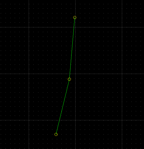
Some years ago I create a simple program that import a log file and create a dxf file where the log points are circles connected by lines.
It turned to be very useful various times.
MDI comands, by order:
python program:
João
It turned to be very useful various times.
MDI comands, by order:
(LOGOPEN,filename.txt)
(log,#<_x> ,#<_y> )
(logclose)
python program:
import csv
import sys
import ezdxf


f = open('filename.txt', 'rt')
try:

    teste= list(csv.reader(f))
    drawing = ezdxf.new(dxfversion='AC1024')
    modelspace = drawing.modelspace()
    drawing.layers.new('circle', dxfattribs={'color': 2})
    drawing.layers.new('line', dxfattribs={'color': 3})


   # print (teste[0],teste[1])
    i=0
    for point in range(0,len(teste)-1):
        modelspace.add_line(teste[i],teste[i+1],dxfattribs={ 'layer': 'line'})
        i=i+1

    for point in range(0,len(teste)):
        modelspace.add_circle(teste[point],3,dxfattribs={ 'layer': 'circle'})


finally:
    f.close()
    drawing.saveas('log2dxf.dxf')
João
Attachments:
Last edit: 24 Feb 2022 18:44 by jtc.
The following user(s) said Thank You: robertspark
Please Log in or Create an account to join the conversation.
- robertspark
- Offline
- Platinum Member
-
Less
More
- Posts: 915
- Thank you received: 216
24 Feb 2022 22:06 #235750
by robertspark
Replied by robertspark on topic Creating DXF's from probing points
Please Log in or Create an account to join the conversation.
Time to create page: 0.140 seconds