- Hardware & Machines
- CNC Machines
- Plasma & Laser
- External offsets - Elements to cut are different heights
External offsets - Elements to cut are different heights
- rodw
-
 Topic Author
- Away
- Platinum Member
-

Less
More
- Posts: 12036
- Thank you received: 4108
08 Jul 2018 06:44 - 08 Jul 2018 06:44 #113789
by rodw
External offsets - Elements to cut are different heights was created by rodw
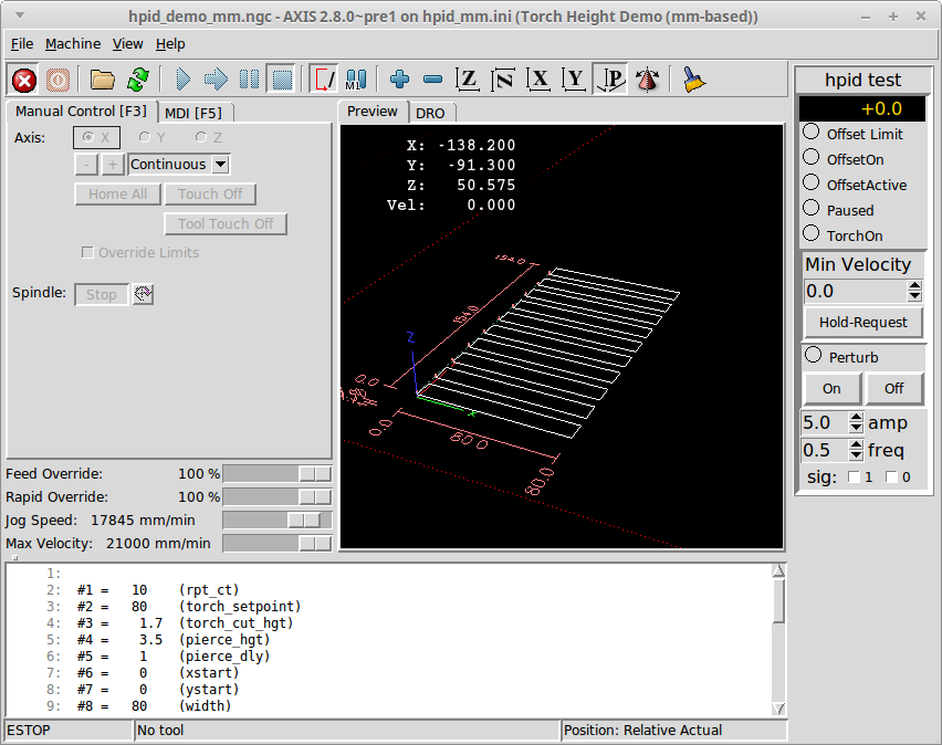
Hi guys, I've seen this before and I'm pretty sure its a configuration issue or work offsets or the like. I've been building a new standard external offsets config using as close as I can to the default interface. There is a standard cut file that comes with the sim that looks like this
But on my new config, it looks like this.
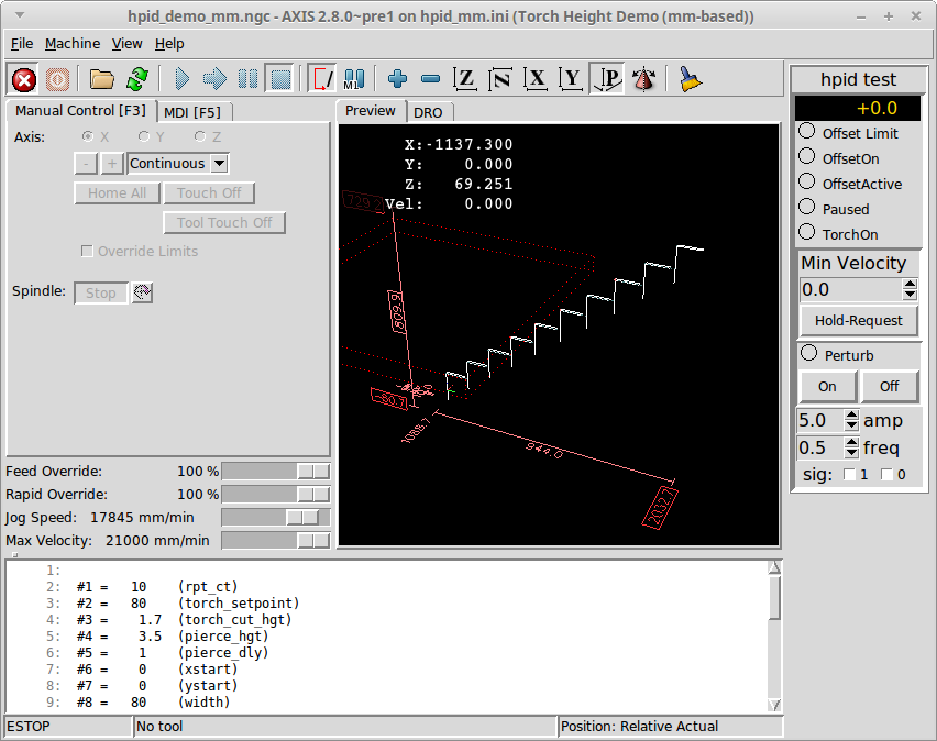
I'm sure its something I've done in the config as the files are identical and changing back to an older config renders it correctly. The machine complains about the Z axis being out of range if I try to cut this.
Any ideas?
But on my new config, it looks like this.
I'm sure its something I've done in the config as the files are identical and changing back to an older config renders it correctly. The machine complains about the Z axis being out of range if I try to cut this.
Any ideas?
Last edit: 08 Jul 2018 06:44 by rodw.
Please Log in or Create an account to join the conversation.
- rodw
-
Topic Author
- Away
- Platinum Member
-
Less
More
- Posts: 12036
- Thank you received: 4108
08 Jul 2018 06:56 #113791
by rodw
Replied by rodw on topic External offsets - Elements to cut are different heights
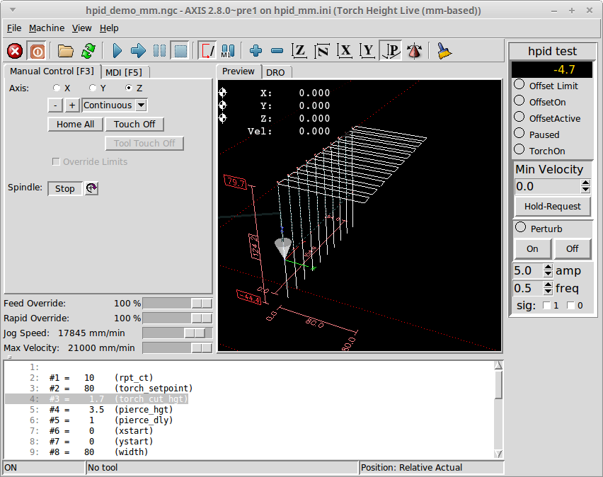
Strange, I found I was missing some info in my [TRAJ] section of my ini file so I added the last 3 lines to this
Improved it, and no longer stepped on different levels,but still higher than the material surface by a long way. (The Tool is on the surface)
[TRAJ]
COORDINATES =  X Y Z
LINEAR_UNITS = mm
ANGULAR_UNITS = degree

#added these lines below
CYCLE_TIME = 0.010
DEFAULT_LINEAR_VELOCITY = 300
MAX_LINEAR_VELOCITY = 300
Improved it, and no longer stepped on different levels,but still higher than the material surface by a long way. (The Tool is on the surface)
Please Log in or Create an account to join the conversation.
- andypugh
-

- Offline
- Moderator
-

Less
More
- Posts: 19879
- Thank you received: 4643
09 Jul 2018 13:44 #113873
by andypugh
Replied by andypugh on topic External offsets - Elements to cut are different heights
A top height of 79.7 and a pierce height of 3.5 makes me wonder about a mm/inch mix-up somewhere.
Please Log in or Create an account to join the conversation.
- rodw
-
Topic Author
- Away
- Platinum Member
-
Less
More
- Posts: 12036
- Thank you received: 4108
09 Jul 2018 14:37 #113877
by rodw
Quite possibly. This particular gcode file is an included external offsets demo file for metric machines which is just a wrapper around an imperial subroutine. Come to think of it, I wrote the wrapper! I did make a change as we had missed a hardcoded imperial tolerance so maybe I broke it.
Its kinda like the path is rendered at the wrong end of the axis.
It does not explain why the sim my machine is based on displays the file correctly. Are there config settings that impact on a gremlin display?
I opened an old file in a gmoccappy config today which was a nest of 5 parts and it was displaying the same as the stepped screen dump above. I had a good look at both configs and could not see any obvious differences. I ran a dry cut with the plasma off and it cut the nest OK so its more of a render thing.
Replied by rodw on topic External offsets - Elements to cut are different heights
A top height of 79.7 and a pierce height of 3.5 makes me wonder about a mm/inch mix-up somewhere.
Quite possibly. This particular gcode file is an included external offsets demo file for metric machines which is just a wrapper around an imperial subroutine. Come to think of it, I wrote the wrapper! I did make a change as we had missed a hardcoded imperial tolerance so maybe I broke it.
Its kinda like the path is rendered at the wrong end of the axis.
It does not explain why the sim my machine is based on displays the file correctly. Are there config settings that impact on a gremlin display?
I opened an old file in a gmoccappy config today which was a nest of 5 parts and it was displaying the same as the stepped screen dump above. I had a good look at both configs and could not see any obvious differences. I ran a dry cut with the plasma off and it cut the nest OK so its more of a render thing.
Please Log in or Create an account to join the conversation.
- rodw
-
Topic Author
- Away
- Platinum Member
-
Less
More
- Posts: 12036
- Thank you received: 4108
11 Jul 2018 21:21 #114030
by rodw
Replied by rodw on topic External offsets - Elements to cut are different heights
I'm pretty sure this is something to do with the probing for the surface as in the sim, this code is commented out. I think there is a solution as I'm sure this has been discussed on the forum but I can't remember where. Grotius is also mentioning it on another thread. forum.linuxcnc.org/38-general-linuxcnc-q...tion?start=20#114022
Please Log in or Create an account to join the conversation.
Moderators: snowgoer540
- Hardware & Machines
- CNC Machines
- Plasma & Laser
- External offsets - Elements to cut are different heights
Time to create page: 0.185 seconds