Halscope of dv/dt during a kerf crossing
- mkardasi
- Offline
- Senior Member
-

Less
More
- Posts: 48
- Thank you received: 18
02 Jul 2019 23:03 #138453
by mkardasi
Halscope of dv/dt during a kerf crossing was created by mkardasi
This is a branch of
Plasmac's Kerf Crossing
which turned into a discussion of dv/dt as the more appropriate algorithm. I would like to continue the discussion relevant to dv/dt for arc voltage here.
Please Log in or Create an account to join the conversation.
- mkardasi
- Offline
- Senior Member
-
Less
More
- Posts: 48
- Thank you received: 18
02 Jul 2019 23:31 - 02 Jul 2019 23:41 #138459
by mkardasi
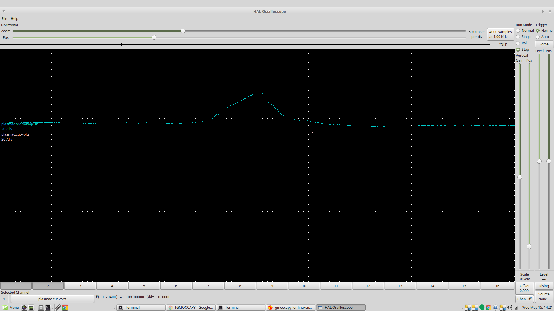
Indeed, however, dv/dt is currently computed using (tvolts - avgvolts)/fperiod. Unless I can clean up tvolts increasing N samples will have little affect on a stable dv/dt. I have a much better capture attached see the annotation below.
My thoughts exactly! Phil mentioned what to modify to increase the range of his algorithm, which does exactly what you described. I will revisit it once I have a chance. I agree a moving avg inherently adds to delay to the resultant signal and intuitively that might cause problems when "real-time" is a consideration. I just don't have enough Halscope time to corroborate...
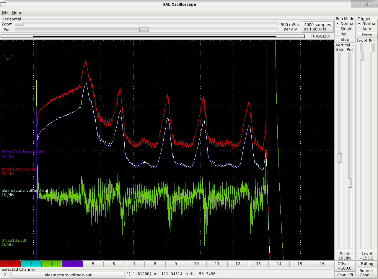
Here is my most recent capture of kerf crossing using dv/dt. I concluded that the noise is from the PAC supply so I disabled encoder.filter. plasma:arc-voltage-out is raw, thcad10.torch-volts is filtered with lowpass.gain 0.145, N samples = 10. To me this reflects a far better signal from which we can extrapolate.
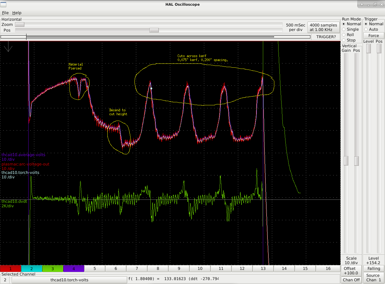
Replied by mkardasi on topic Halscope of dv/dt during a kerf crossing
For mkardasi I'm a bit worried about the variation in the signal. I wonder if you should repeat the test with 100 readings and 1000 readings for the moving average. In theory, that should smooth out the average more.
Indeed, however, dv/dt is currently computed using (tvolts - avgvolts)/fperiod. Unless I can clean up tvolts increasing N samples will have little affect on a stable dv/dt. I have a much better capture attached see the annotation below.
Thinking that if there are no fluctuations bigger than 5 to 6V with the THC on, setting the THC to lock if the voltage changes by over 8 or 10V should do the trick nicely. Setting that inside of 2 readings might not work properly, but inside of 5 to 10 reading might work.
Averaging 1000 samples is not an option as that is 1 second and when cutting at 6m/minute that would happen after 100mm of cut. At 100 samples that is still 1cm and at 10 samples 1mm .
My thoughts exactly! Phil mentioned what to modify to increase the range of his algorithm, which does exactly what you described. I will revisit it once I have a chance. I agree a moving avg inherently adds to delay to the resultant signal and intuitively that might cause problems when "real-time" is a consideration. I just don't have enough Halscope time to corroborate...
Here is my most recent capture of kerf crossing using dv/dt. I concluded that the noise is from the PAC supply so I disabled encoder.filter. plasma:arc-voltage-out is raw, thcad10.torch-volts is filtered with lowpass.gain 0.145, N samples = 10. To me this reflects a far better signal from which we can extrapolate.
Attachments:
Last edit: 02 Jul 2019 23:41 by mkardasi.
The following user(s) said Thank You: tommylight
Please Log in or Create an account to join the conversation.
- rodw
-

- Offline
- Platinum Member
-

Less
More
- Posts: 12047
- Thank you received: 4113
02 Jul 2019 23:45 #138463
by rodw
Replied by rodw on topic Halscope of dv/dt during a kerf crossing
Oops, I missed the note on the originating thread. So reposting below:
I agree 1 second might be too long but maybe 10 readings (0.01 sec) is too short....
This is probably as good a plot as any of an Arc establishment and cutting normally without THC (Everlast 50 amp)
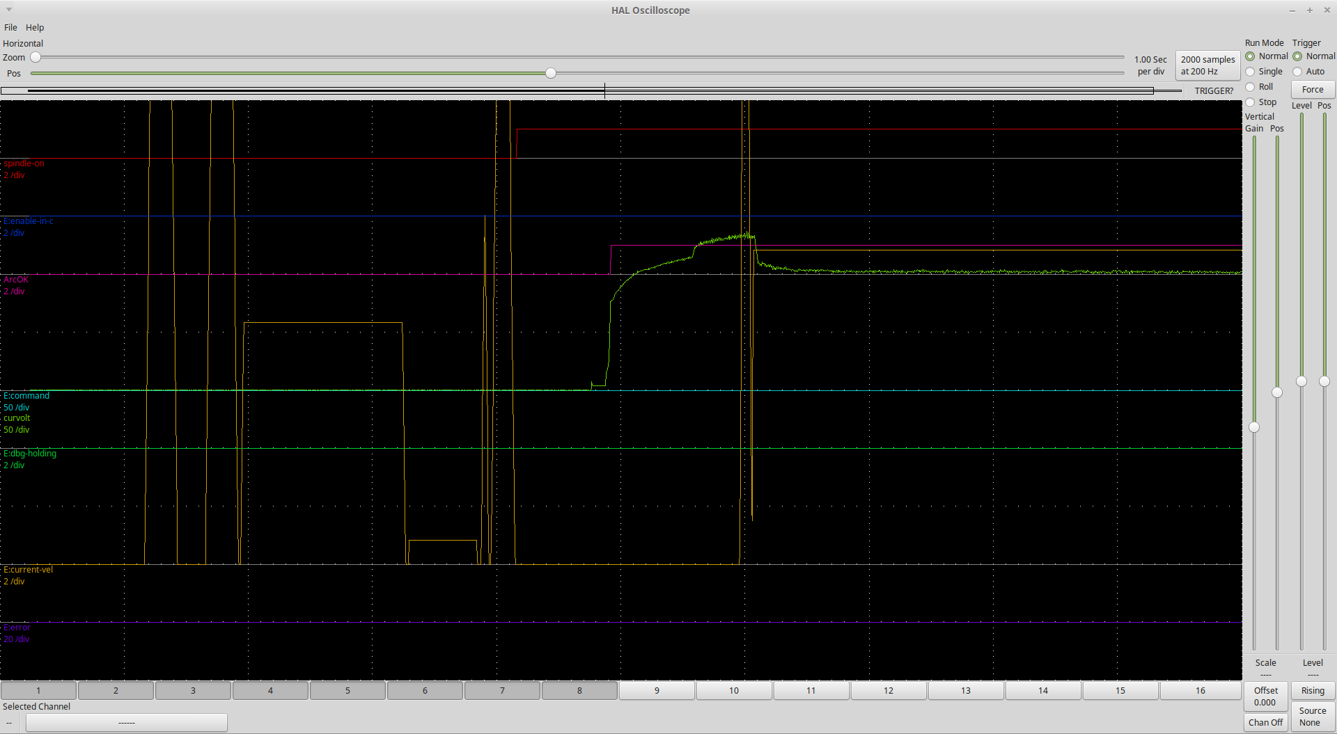
And arc establishment, crossing a kerf and running off a sheet
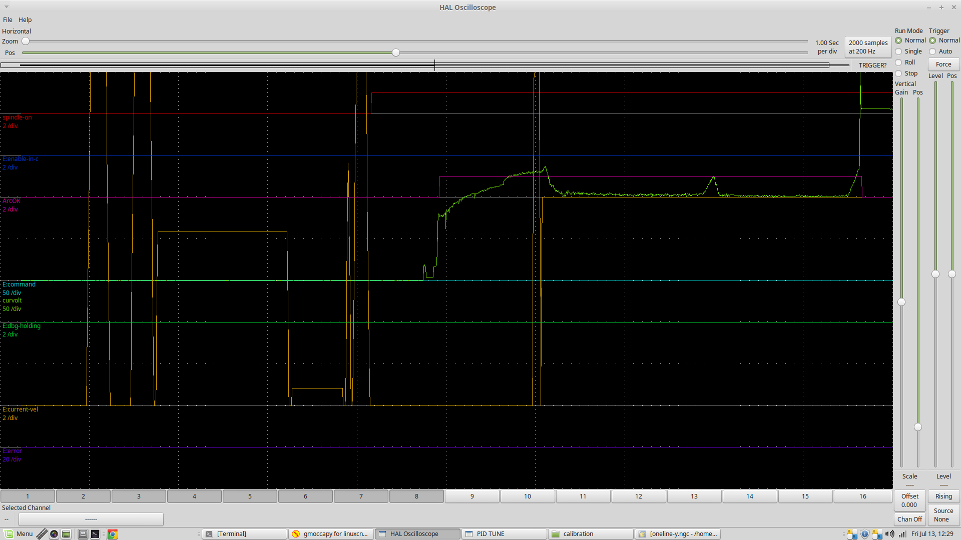
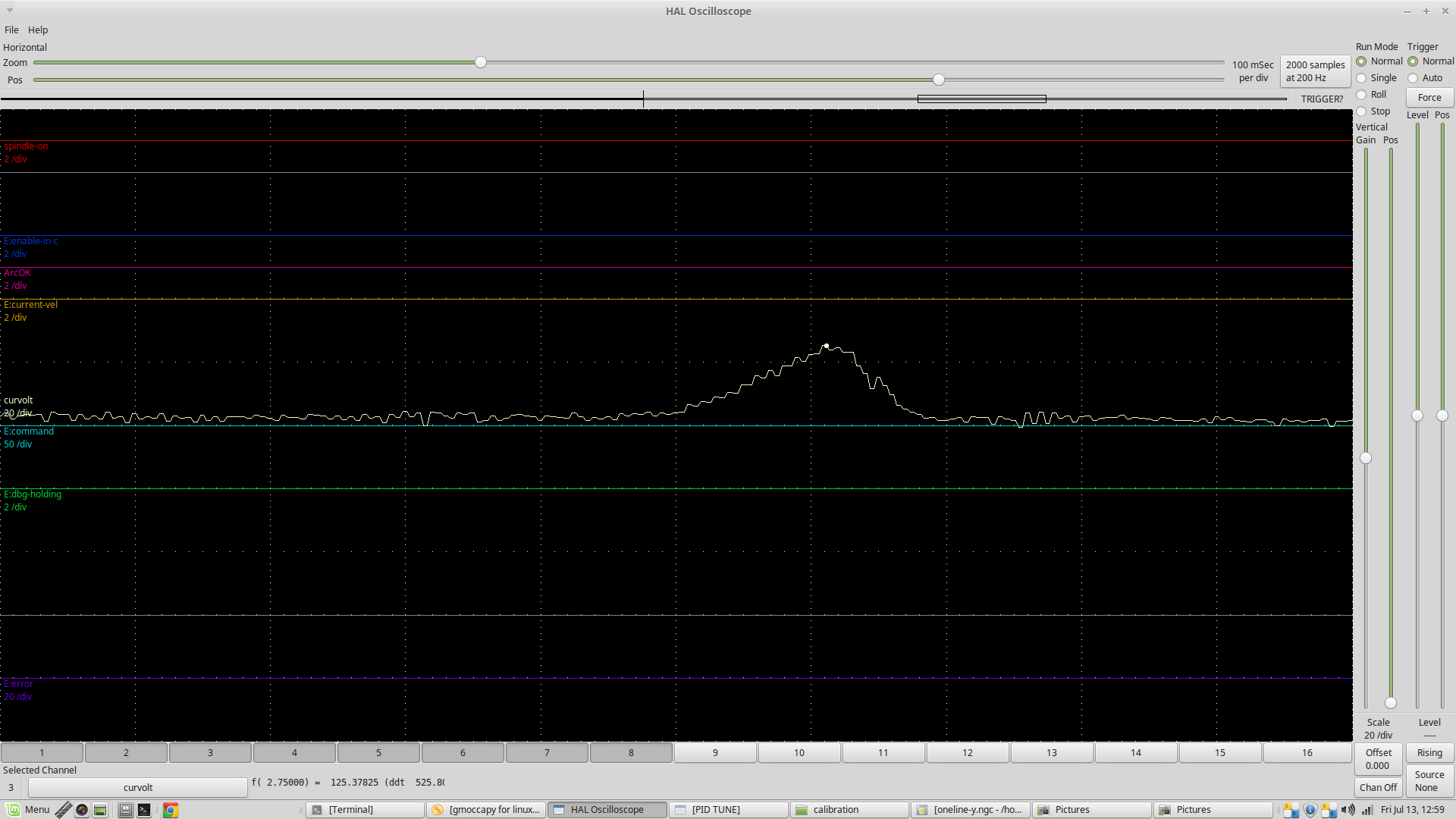
Close up
And now with plasmac close up of the original one we've been discussing no THC (Thermal Dynamics A120)
So you can see the arc voltage peaks quickly during piercing (why we use a THC-on delay ) then stays very stable.
Also its clear that better quality machines have a much cleaner torch voltage but some of that could be due to me adding stuff to counter noise on the Everlast. So you have a much better process control signal if you spend the money.
The rate of change is a much better indicator of kerf crossing because it is several orders of magnitude higher than what can happen from normal warpage (but with the plasmac THC, this should be very little).
We are going to nail this eventually.
I agree 1 second might be too long but maybe 10 readings (0.01 sec) is too short....
This is probably as good a plot as any of an Arc establishment and cutting normally without THC (Everlast 50 amp)
And arc establishment, crossing a kerf and running off a sheet
Close up
And now with plasmac close up of the original one we've been discussing no THC (Thermal Dynamics A120)
So you can see the arc voltage peaks quickly during piercing (why we use a THC-on delay ) then stays very stable.
Also its clear that better quality machines have a much cleaner torch voltage but some of that could be due to me adding stuff to counter noise on the Everlast. So you have a much better process control signal if you spend the money.
The rate of change is a much better indicator of kerf crossing because it is several orders of magnitude higher than what can happen from normal warpage (but with the plasmac THC, this should be very little).
We are going to nail this eventually.
Please Log in or Create an account to join the conversation.
- rodw
-
- Offline
- Platinum Member
-
Less
More
- Posts: 12047
- Thank you received: 4113
02 Jul 2019 23:51 #138466
by rodw
Can you tell us about your plasma hardware (make, model, HF or Blowback start, voltage divider?)
Personally, I think from my experience adding a mains EMI/RFI filter as the power enters your control box will make a huge difference to the noise in your signal. You really need to deal with that first if you can as its a very poor process control variable in its present state.
Replied by rodw on topic Halscope of dv/dt during a kerf crossing
For mkardasi I'm a bit worried about the variation in the signal. I wonder if you should repeat the test with 100 readings and 1000 readings for the moving average. In theory, that should smooth out the average more.
Indeed, however, dv/dt is currently computed using (tvolts - avgvolts)/fperiod. Unless I can clean up tvolts increasing N samples will have little affect on a stable dv/dt. I have a much better capture attached see the annotation below.
Thinking that if there are no fluctuations bigger than 5 to 6V with the THC on, setting the THC to lock if the voltage changes by over 8 or 10V should do the trick nicely. Setting that inside of 2 readings might not work properly, but inside of 5 to 10 reading might work.
Averaging 1000 samples is not an option as that is 1 second and when cutting at 6m/minute that would happen after 100mm of cut. At 100 samples that is still 1cm and at 10 samples 1mm .
My thoughts exactly! Phil mentioned what to modify to increase the range of his algorithm, which does exactly what you described. I will revisit it once I have a chance. I agree a moving avg inherently adds to delay to the resultant signal and intuitively that might cause problems when "real-time" is a consideration. I just don't have enough Halscope time to corroborate...
Here is my most recent capture of kerf crossing using dv/dt. I concluded that the noise is from the PAC supply so I disabled encoder.filter. plasma:arc-voltage-out is raw, thcad10.torch-volts is filtered with lowpass.gain 0.145, N samples = 10. To me this reflects a far better signal from which we can extrapolate.
Can you tell us about your plasma hardware (make, model, HF or Blowback start, voltage divider?)
Personally, I think from my experience adding a mains EMI/RFI filter as the power enters your control box will make a huge difference to the noise in your signal. You really need to deal with that first if you can as its a very poor process control variable in its present state.
Please Log in or Create an account to join the conversation.
- mkardasi
- Offline
- Senior Member
-
Less
More
- Posts: 48
- Thank you received: 18
03 Jul 2019 00:28 - 03 Jul 2019 00:28 #138473
by mkardasi
Machine is an ESAB PCM-875, it is HF start with a native CNC output that has a 20:1 voltage divider. Yes I agree the signal is noisy and far from optimal. At present I do not have an RFI/mains filter for the control box. I am using a 5v cell phone PSU for the MESA hardware. I would have to acquire a mains filter...all I have on hand at the moment is a few ferrites that is could loop the incoming mains power through.
I did test the MESA hardware with the ESAB powered off and my arc voltage dithers 200mV, with the ESAB on, but not cutting, dither is the same.
So, yes I see where you are going with is. It is either the native noise from the ESAB or it it is noise being coupled through. I will make some modifications and report back.
Replied by mkardasi on topic Halscope of dv/dt during a kerf crossing
[
Can you tell us about your plasma hardware (make, model, HF or Blowback start, voltage divider?)
Personally, I think from my experience adding a mains EMI/RFI filter as the power enters your control box will make a huge difference to the noise in your signal. You really need to deal with that first if you can as its a very poor process control variable in its present state.
Machine is an ESAB PCM-875, it is HF start with a native CNC output that has a 20:1 voltage divider. Yes I agree the signal is noisy and far from optimal. At present I do not have an RFI/mains filter for the control box. I am using a 5v cell phone PSU for the MESA hardware. I would have to acquire a mains filter...all I have on hand at the moment is a few ferrites that is could loop the incoming mains power through.
I did test the MESA hardware with the ESAB powered off and my arc voltage dithers 200mV, with the ESAB on, but not cutting, dither is the same.
So, yes I see where you are going with is. It is either the native noise from the ESAB or it it is noise being coupled through. I will make some modifications and report back.
Last edit: 03 Jul 2019 00:28 by mkardasi.
Please Log in or Create an account to join the conversation.
- mkardasi
- Offline
- Senior Member
-
Less
More
- Posts: 48
- Thank you received: 18
03 Jul 2019 02:21 #138482
by mkardasi
Replied by mkardasi on topic Halscope of dv/dt during a kerf crossing
Following up to Rod's suggestions, that I might have interference on the mains...I plugged the control box and PC into a APC SurgeArrest Professional power strip with built-in surge suppression and EMI filtering. This is the resultant plot, I see no change in SNR: Note that thcad10.torch-volt is now the raw signal from the ESAB PAC supply, plasmac.arc-voltage-out is filtered with lowpass.gain = 0.118 & thcad10.average-volts is the moving avg of the raw signal with N=10 samples.
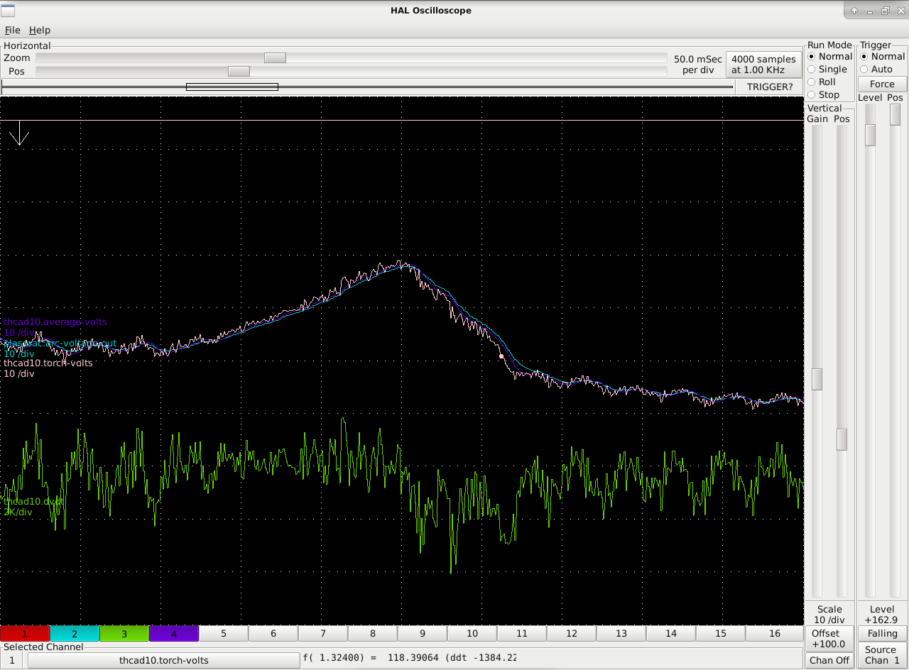
This is a zoom of the first kerf crossing.
My conclusion is that I don't believe that my signal noise is extraneous, there is nothing I can do about it in hardware (that I can figure out). Rather it is what is delivered by my PAC supply that is a design cira <1998. Going forward I intend on using lowpass to filter the incoming signal from the PAC and then route it into the component capable of dv/dt for further analysis.
The following user(s) said Thank You: tommylight
Please Log in or Create an account to join the conversation.
- tommylight
-

- Away
- Moderator
-

Less
More
- Posts: 21760
- Thank you received: 7435
03 Jul 2019 09:54 #138507
by tommylight
Replied by tommylight on topic Halscope of dv/dt during a kerf crossing
You can add a capacitor to the THCAD, but that would mess up reaction times, so not advisable.
Much better to use a lowpass and tune it.
That noise can be from the plasma causing fluctuations in the mains voltage, and most plasmas do not use filtering on the output.
Is it an inverter or a transformer type? The only difference is the noise will be at 50 or 60Hz for the transformer one and at much higher frequency for the inverter type.
Please Log in or Create an account to join the conversation.
- mkardasi
- Offline
- Senior Member
-
Less
More
- Posts: 48
- Thank you received: 18
03 Jul 2019 13:03 #138521
by mkardasi
Replied by mkardasi on topic Halscope of dv/dt during a kerf crossing
It's an inverter.
Please Log in or Create an account to join the conversation.
- andypugh
-

- Offline
- Moderator
-
Less
More
- Posts: 19879
- Thank you received: 4644
03 Jul 2019 14:15 #138531
by andypugh
Replied by andypugh on topic Halscope of dv/dt during a kerf crossing
calculating dv/dt is inherently very noisy. Here is an algorithm that I developed to solve a similar problem. (I don't claim to be the _first_ to develop it, though)
There are well-established algorithms to fit a polynomial to a sample of N data points, using a least-squared fit and to an arbitrary degree of polynomial.
The gradient of a polynomial A + Bx + Cx^2 + Dx^3 is simply the differential of that polynomial: ie B + 2.Cx + 3.Dx*2
Note that in this case the polynomial is Volts = f(t) and the derivative is therefore dV/dt as a function of t.
This approach has two advantages that can (sometimes) make up for the large increase in computational overhead:
1) The gradient at any point is based on a lot more data points than a single sample Dx/Dy
2) You can calculate the gradient for any X inside or outside the current sample range (with greatest confidence in the middle of the range). This means that you can get a reasonably well-behaved gradient at the current time, avoiding some of the lag inherent in a rolling average.
There is some sample C code here to do the curve fitting, (note that half the code there is concerned with inputting the data and printing the result)
It is reasonably easy to imagine a linuxCNC .comp that takes parameters for degree of polynomial and sample length and where in the sample to calculate the gradient and that takes a sample every servo period and outputs the gradient.
Please Log in or Create an account to join the conversation.
- andypugh
-
- Offline
- Moderator
-
Less
More
- Posts: 19879
- Thank you received: 4644
03 Jul 2019 14:15 #138532
by andypugh
Replied by andypugh on topic Halscope of dv/dt during a kerf crossing
calculating dv/dt is inherently very noisy. Here is an algorithm that I developed to solve a similar problem. (I don't claim to be the _first_ to develop it, though)
There are well-established algorithms to fit a polynomial to a sample of N data points, using a least-squared fit and to an arbitrary degree of polynomial.
The gradient of a polynomial A + Bx + Cx^2 + Dx^3 is simply the differential of that polynomial: ie B + 2.Cx + 3.Dx*2
Note that in this case the polynomial is Volts = f(t) and the derivative is therefore dV/dt as a function of t.
This approach has two advantages that can (sometimes) make up for the large increase in computational overhead:
1) The gradient at any point is based on a lot more data points than a single sample Dx/Dy
2) You can calculate the gradient for any X inside or outside the current sample range (with greatest confidence in the middle of the range). This means that you can get a reasonably well-behaved gradient at the current time, avoiding some of the lag inherent in a rolling average.
There is some sample C code here to do the curve fitting, (note that half the code there is concerned with inputting the data and printing the result)
It is reasonably easy to imagine a linuxCNC .comp that takes parameters for degree of polynomial and sample length and where in the sample to calculate the gradient and that takes a sample every servo period and outputs the gradient.
www.bragitoff.com/2018/06/polynomial-fitting-c-program/
Please Log in or Create an account to join the conversation.
Moderators: snowgoer540
Time to create page: 0.281 seconds