Downdraft design questions

More
5 years 11 months ago #188690 by txtrone
Replied by txtrone on topic Downdraft design questions
Correct. I should have posted that as a question to Himarc3D.

A brand he mentioned, SMC, makes industrial versions with manifold and bus wiring combined. If this experiment works with the cheap 5/2 valves that I bought on Amazon, I would be willing to order a custom 8 station 5/2 valve with the correct manifold and wire harness.

Please Log in or Create an account to join the conversation.
More
5 years 11 months ago #188738 by rodw
Replied by rodw on topic Downdraft design questions
Ok, unzip this folder into your config folder. it will create a folder called gantry which is a basic sim I've edited to be your 6' x 12' table.
Navigate to that folder in a terminal window. type
Code:
sudo halcompile --install ddraft4x2.comp
Check for errors and resolve or report back
turn on, home all. Load the ddraft.ngc file in the gantry folder.
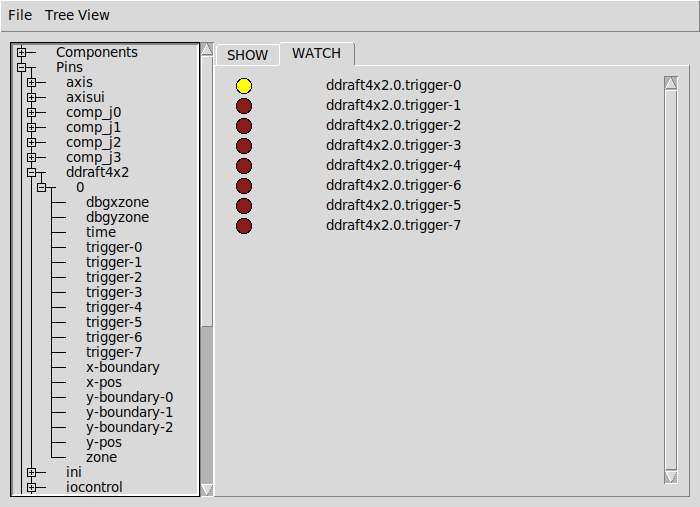
From the machine menu, select show hal configuration. Select the watch tab.
in the tree for pins, find the ddraft4x2.0 component and click on all 8 triggers (numbered 0 to 7) to watch each pin.

run the ngc file and watch the magic happen!

Next step is to connect each trigger pin to a real output pin. (Remember what I said about diodes). I generally would do it like this:
Code:
net zone0 <= ddraft4x2.0.trigger-0 net zone0 => hm2_7i76e.0.7i76.0.0.output-00

So if you wish to change the zone boundaries you can edit ddraft4x2.hal file to change them

To go live, copy ddraft4x2.hal to your config folder and edit your ini file in a text editor (I use Geany!) and add it to the [HAL] section
Code:
[HAL] HALFILE = ddraft4x2.hal

Good luck!


File Attachment:

File Name: ddraft-sim.tar.gz
File Size:7.12 KB
The following user(s) said Thank You: txtrone

Please Log in or Create an account to join the conversation.

More
5 years 11 months ago #188824 by txtrone
Replied by txtrone on topic Downdraft design questions

rodw wrote: Next step is to connect each trigger pin to a real output pin. (Remember what I said about diodes). I generally would do it like this:

Code:
net zone0 <= ddraft4x2.0.trigger-0 net zone0 => hm2_7i76e.0.7i76.0.0.output-00


I got it loaded and when I jog around the 'table' (simulated only since I have nothing connected to my Mesa card yet) the pins change as I moved from section to section. That's good stuff!

Refresh my memory, should I use some LEDs on the Mesa card to prove that the outputs are firing the same as the pins in the HAL confifuration?

Also, where does the is 'net zone' code belong? Is that the example code for zone 0 only? Should it look like this when I am finished?
Code:
net zone0 <= ddraft4x2.0.trigger-0 net zone0 => hm2_7i76e.0.7i76.0.0.output-00 net zone1 <= ddraft4x2.0.trigger-1 net zone1 => hm2_7i76e.0.7i76.0.0.output-01 net zone2 <= ddraft4x2.0.trigger-2 net zone2 => hm2_7i76e.0.7i76.0.0.output-02 net zone3 <= ddraft4x2.0.trigger-3 net zone3 => hm2_7i76e.0.7i76.0.0.output-03 net zone4 <= ddraft4x2.0.trigger-4 net zone4 => hm2_7i76e.0.7i76.0.0.output-04 net zone5 <= ddraft4x2.0.trigger-5 net zone5 => hm2_7i76e.0.7i76.0.0.output-05 net zone6 <= ddraft4x2.0.trigger-6 net zone6 => hm2_7i76e.0.7i76.0.0.output-06 net zone7 <= ddraft4x2.0.trigger-7 net zone7 => hm2_7i76e.0.7i76.0.0.output-07

Please Log in or Create an account to join the conversation.

More
5 years 11 months ago #188832 by rodw
Replied by rodw on topic Downdraft design questions
That was painless!

That looks right. Yes, I only did one example! The outputs may need to be different as you might already be using a pin for torch on or something.

If you upgrade linuxcnc, you may need to redo the halcompile step as the component is not native to linuxcnc.

There is also a separate zone pin that publishes a numeric number for the current zone. If you were ambitious you could modify your GUI to display the number from that pin. Or add a row of GUI LED's for each zone.

Very cool. Can't wait to see how it works for you!

Please Log in or Create an account to join the conversation.

More
5 years 11 months ago #188833 by rodw
Replied by rodw on topic Downdraft design questions

txtrone wrote: Refresh my memory, should I use some LEDs on the Mesa card to prove that the outputs are firing the same as the pins in the HAL confifuration?

Also, where does the is 'net zone' code belong? Is that the example code for zone 0 only? Should it look like this when I am finished?


I would keep all the connections in the ddraft4x2.hal file
I have used a 22mmm mount 24V LED light to confirm working but to use a LED you would need a 2.2k 1/2 W current limiting resistor

Please Log in or Create an account to join the conversation.

More
5 years 11 months ago #188835 by rodw
Replied by rodw on topic Downdraft design questions
You could also confirm output operation just by jogging in to each zone and use a multimeter on the output

Please Log in or Create an account to join the conversation.

Moderators: snowgoer540
Time to create page: 0.182 seconds
Powered by Kunena Forum