happy new year guys
- love0ff
- Offline
- New Member
-

Less
More
- Posts: 3
- Thank you received: 2
01 Jan 2021 21:54 #193758
by love0ff
happy new year guys was created by love0ff
Hi guys, happy new year
I can't thank you enough for your time and effort went onto this forum all these years to help us building our machines and make dreams come true. I wish you all safe and happy new year
so,I was following thefabricator03 Example wiring diagram Post No:#148670 I colored some lines (red and green ) to make it clear and just want to make sure if everything is right.
I'd appreciate any feedback guys
The following user(s) said Thank You: tommylight
Please Log in or Create an account to join the conversation.
- tommylight
-

- Away
- Moderator
-

Less
More
- Posts: 21718
- Thank you received: 7422
01 Jan 2021 22:23 #193760
by tommylight
Replied by tommylight on topic happy new year guys
Looks good, except for TB1 pin 5, should be wired to pin 1.
It will work as is, but not preferred since the VIN and VFIELD can be separated by a jumper so moving that jumper might cause issues.
It will work as is, but not preferred since the VIN and VFIELD can be separated by a jumper so moving that jumper might cause issues.
Please Log in or Create an account to join the conversation.
- rodw
-

- Offline
- Platinum Member
-

Less
More
- Posts: 12012
- Thank you received: 4096
01 Jan 2021 22:44 #193764
by rodw
Replied by rodw on topic happy new year guys
Revised Hypersensing circuit for water tables. add the 24K 5 W resistor
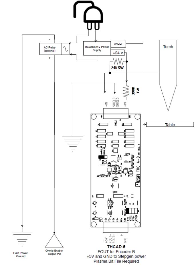
Also add a 90 Ohm 10 W pull down resistor from the Ohmic input (Input-15) to 0 volt
You can also use 3 x 270 Ohm 5W resistors in parallel (to give 90 Ohms 15 Watts)
Mount all these resistors in the air, they could get hot!
Also add a 90 Ohm 10 W pull down resistor from the Ohmic input (Input-15) to 0 volt
You can also use 3 x 270 Ohm 5W resistors in parallel (to give 90 Ohms 15 Watts)
Mount all these resistors in the air, they could get hot!
Please Log in or Create an account to join the conversation.
- love0ff
- Offline
- New Member
-
Less
More
- Posts: 3
- Thank you received: 2
01 Mar 2021 14:21 - 01 Mar 2021 15:28 #200694
by love0ff
Replied by love0ff on topic happy new year guys
Hi,guysIt's been a long time
I thank I've reached the point where I need help
My question is do I need to set jumpers W10, W11 and W13 to single or differential mode, I just copied and followed WIRINGDIAGRAM as is
The only thing I changed I use 48vdc switching power supply to Power stepper driver instead of toroidal transformer because I couldn't get one, if this is Will change or affect in any way on WIRING DIAGRAM Please inform me
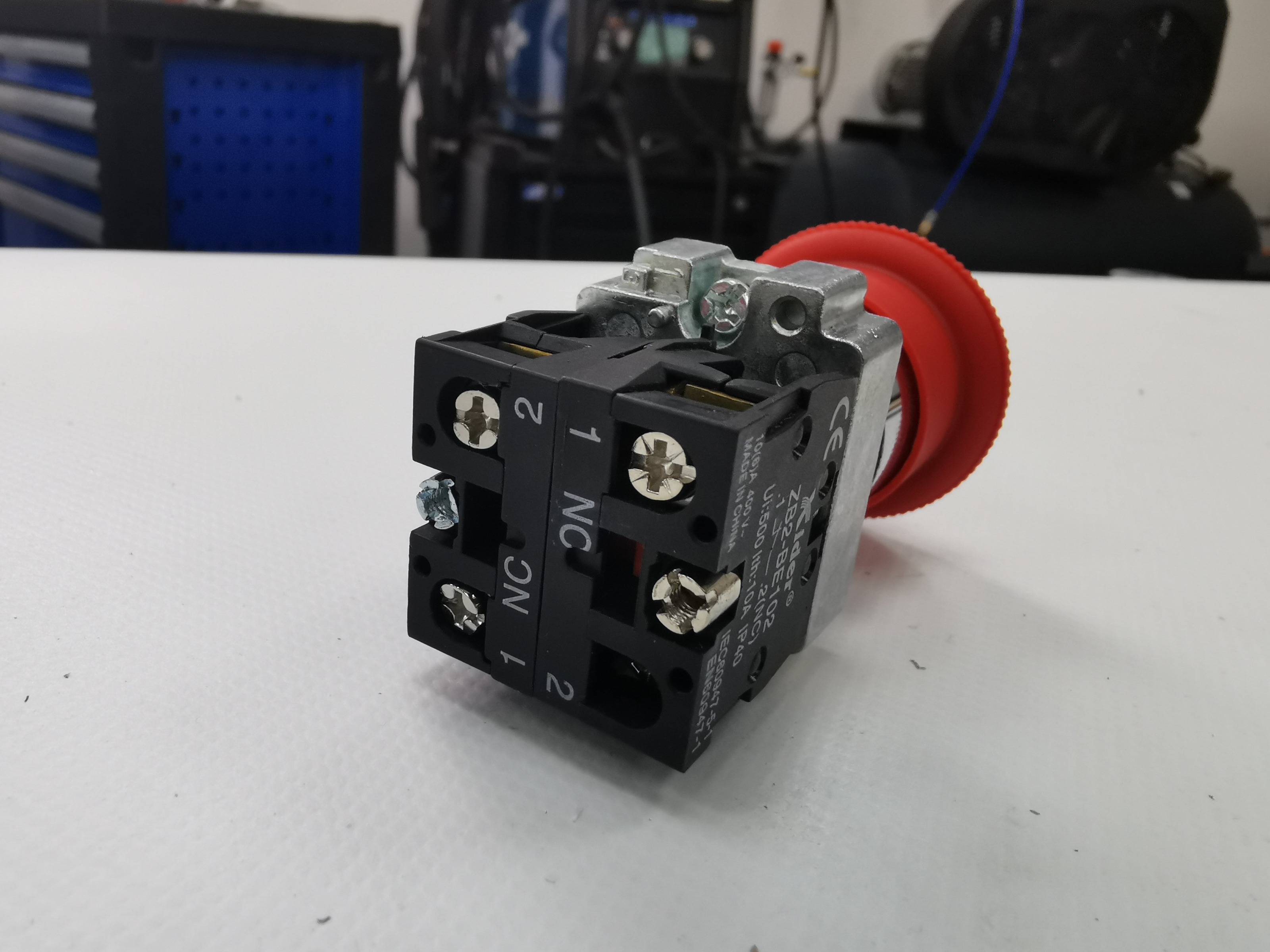
I really confused about E-stop It is 2 NC. I attached a picture of what I have and want to make sure if this is the right one
Thanks rodw for Hypersensing
I thank I've reached the point where I need help
My question is do I need to set jumpers W10, W11 and W13 to single or differential mode, I just copied and followed WIRINGDIAGRAM as is
The only thing I changed I use 48vdc switching power supply to Power stepper driver instead of toroidal transformer because I couldn't get one, if this is Will change or affect in any way on WIRING DIAGRAM Please inform me
I really confused about E-stop It is 2 NC. I attached a picture of what I have and want to make sure if this is the right one
Thanks rodw for Hypersensing
Last edit: 01 Mar 2021 15:28 by love0ff. Reason: ok
The following user(s) said Thank You: rodw
Please Log in or Create an account to join the conversation.
- robertspark
- Offline
- Platinum Member
-
Less
More
- Posts: 915
- Thank you received: 216
01 Mar 2021 16:19 #200709
by robertspark
Replied by robertspark on topic happy new year guys
estop is correct. they are "normally" NC {normally closed} contacts for 2x reasons....
1) you can daisy chain a number of them together so if you hit / trigger one, the whole signal is lost and everything stops
2) more importantly.... if the signal was NO, how would you know that something had failed if the cable had been cut / power lost to the estop circuit.... having it NC means you have a positive confirmation that the circuit is intact / operating and when the signal (voltage) is lost for whatever reason everything is stopped.
someone else will answer the other bits I'm sure:
encoder input = differential mode as it offers better noise / signal immunity
I have not been successful with switched mode power supplies powering stepper motors (but I know 100's if not 1000's of people use them).... but my stepper motor drivers use to sing and squawk under acceleration and breaking (mainly breaking with back EMF generation). I now only use toroidal transformers and the drivers and stepper motors are silent and move fast enough for my needs. YMMV, give it a shot.
Please Log in or Create an account to join the conversation.
Moderators: snowgoer540
Time to create page: 0.185 seconds