Breakaway torch carrier design
- dlv
- Offline
- Junior Member
-

Less
More
- Posts: 38
- Thank you received: 17
02 Jan 2022 23:59 - 03 Jan 2022 00:05 #230594
by dlv
Breakaway torch carrier design was created by dlv
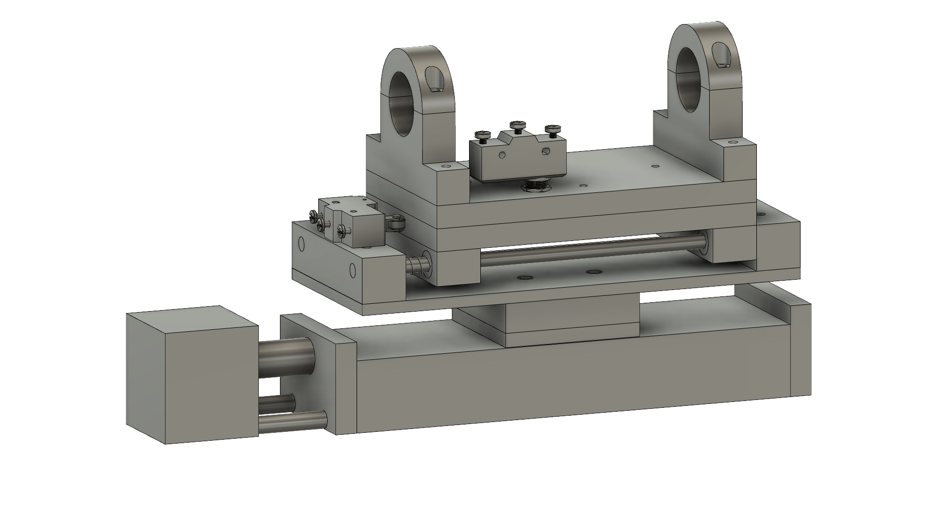
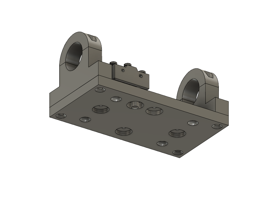
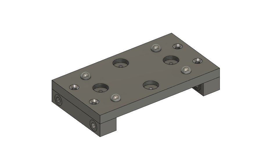
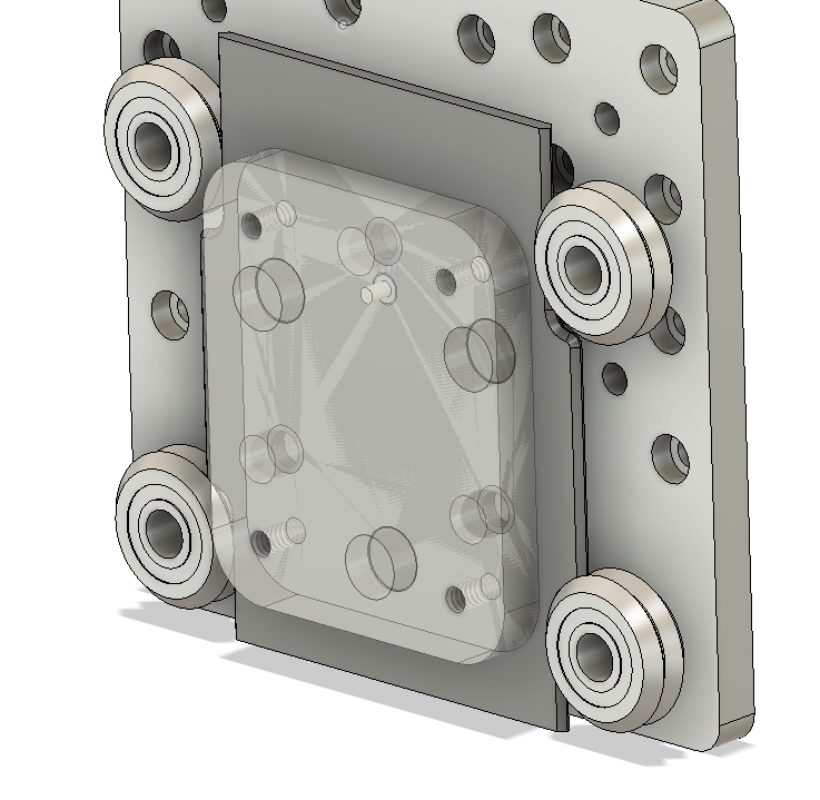
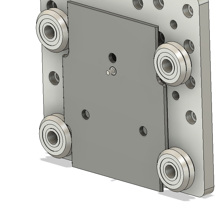
I'm designing a LinuxCNC 5'x5' plasma table and modeled up my torch carrier in Fusion. The design has 8mm linear bearings to allow the torch mount to slide up and make contact on the roller limit switch for material sensing. I've also designed in a magnetic breakaway for the torch holder. Attached are 3D renders of the back plate, breakaway plate and the entire Z-axis assembly.
The breakaway torch holder and the back plate will be indexed on .5" ball bearings mounted in the back plate as shown. I've allowed for up to 4 pairs of opposing magnets (on both the back plate and breakaway). If I find 4 pairs is too strong to allow the torch to breakaway appropriately, I can try 3 or even 2 pair.I have a plunger limit switch mounted through the breakaway plate and contacting on the back plate to signal when the torch breaks away and trigger an Estop.
All the assembly components will all be milled out of aluminum.
In the 3D model you can see how it mounts on the Z-axis gantry which is an OpenBuilds C-beam 20x80 aluminum extrusion linear actuator. That gantry plate on the actuator is only 3"x3" and is leadscrew driven. The Z axis actuator is rated for 26 lbs force. I'm hoping the weight of this assembly (which is a total of 10" long) doesn't put so much moment arm stress on that gantry plate in high acceleration movements. Fingers crossed.
Please feel free to reply with any suggestions for improvement or any problems you see in this design.
Cheers and thanks!
-Dave
Attachments:
Last edit: 03 Jan 2022 00:05 by dlv.
Please Log in or Create an account to join the conversation.
- andypugh
-

- Away
- Moderator
-

Less
More
- Posts: 19874
- Thank you received: 4641
03 Jan 2022 13:17 #230649
by andypugh
Replied by andypugh on topic Breakaway torch carrier design
You might find three balls to be more stable (like the three-legged milking stool).
Also, possibly make the mating part as a groove, so that they can all settle in to a repeatable position (basically somewhat like a touch-probe)
For the carrier rail I have long thought that a (second hand) guided pneumatic cylinder might be a good starting point. Then you can regulate the spring rate (and even vary it during the phases of cutting). They also generally have limit-switch mounting built-in.
An example, just to indicate what I am talking about: www.ebay.co.uk/itm/274683980616
The following user(s) said Thank You: dlv
Please Log in or Create an account to join the conversation.
- dlv
- Offline
- Junior Member
-
Less
More
- Posts: 38
- Thank you received: 17
03 Jan 2022 15:11 #230655
by dlv
Replied by dlv on topic Breakaway torch carrier design
Thanks Andy. Those guided pneumatic cylinders look def look interesting. I've already got the parts for the linear bearing & rods. That idea would have saved me time on the mill tho. At 30-40 bucks I might just grab one of those to play with tho.
I'll give the 3 bearing idea some thought.
Not sure I follow on the groove suggestion though. Are you saying the balls should index into a groove rather than a dimple? My thinking on the ball & dimple is it indexes in all directions. Ball and groove would only index perpendicular to the groove and still freely move along the groove? Maybe I'm just being dense here and you mean something different.
Please Log in or Create an account to join the conversation.
- andypugh
-
- Away
- Moderator
-
Less
More
- Posts: 19874
- Thank you received: 4641
03 Jan 2022 15:17 #230656
by andypugh
Replied by andypugh on topic Breakaway torch carrier design
If the three grooves are at 120 degrees to each other (actually, as long as they are at three different angles) then it is perfectly constrained, but not over-constrained.
The grooves do not need to be very long. Maybe only a couple of mm. Just enough so that there is enough wiggle-room for all 6 flat sides to touch their ball.
TBH for a plasma it probably isn't all that critical, but the touch-probe I just finished has a similar setup that settles to within 1 micron.
The following user(s) said Thank You: dlv
Please Log in or Create an account to join the conversation.
- dlv
- Offline
- Junior Member
-
Less
More
- Posts: 38
- Thank you received: 17
03 Jan 2022 15:26 #230657
by dlv
Replied by dlv on topic Breakaway torch carrier design
Ok yeah now I get it. That makes total sense. Duh! Probably a lot less sensitive to how well I press the balls into their undersized holes and/or machine the dimples to match. To not have any play that was going to need to be precise and I was a little worried about how that might go. It also explains your 3 ball vs 4 ball suggestion a great deal.
Thanks a bunch!
Thanks a bunch!
Please Log in or Create an account to join the conversation.
- RNJFAB
- Offline
- Elite Member
-

Less
More
- Posts: 251
- Thank you received: 59
04 Jan 2022 00:26 #230700
by RNJFAB
Replied by RNJFAB on topic Breakaway torch carrier design
I have tried a few versions of breakaway torch systems, all without much success.
The biggest issue I find is not locating the torch, rather getting it to stay put. I currently have 10 'strong' magnets (20x5mm) holding my torch on and it's not strong enough.
Keen to see how you go with the magnets holding the torch on.
The biggest issue I find is not locating the torch, rather getting it to stay put. I currently have 10 'strong' magnets (20x5mm) holding my torch on and it's not strong enough.
Keen to see how you go with the magnets holding the torch on.
Please Log in or Create an account to join the conversation.
- tommylight
-

- Offline
- Moderator
-
Less
More
- Posts: 21691
- Thank you received: 7413
04 Jan 2022 00:38 #230703
by tommylight
Replied by tommylight on topic Breakaway torch carrier design
I use 1 or 2 magnets yanked out of old hard drives.
Please Log in or Create an account to join the conversation.
- dlv
- Offline
- Junior Member
-
Less
More
- Posts: 38
- Thank you received: 17
04 Jan 2022 00:55 #230705
by dlv
Replied by dlv on topic Breakaway torch carrier design
RNJFAB do you have those magnets on both sides, attracting each other or just a metal plate on one side? They're a LOT stronger if attracting each other. I've got 20x3mm and if I put just two of them together I can't pull them apart. I've got the kind with a hole in the middle.
But full disclosure I haven't built this yet. So I'll definitely update on how it goes.
But full disclosure I haven't built this yet. So I'll definitely update on how it goes.
Please Log in or Create an account to join the conversation.
- spumco
- Offline
- Platinum Member
-

Less
More
- Posts: 2124
- Thank you received: 882
04 Jan 2022 01:18 #230707
by spumco
Replied by spumco on topic Breakaway torch carrier design
Here's a design I made that's cheap, been working well for 4 years and >200k pierces with no accidental activations.
Holes in slider can be easily adjusted (chamfer, size) for an appropriate break-away force in all directions. I found that to get a good 'feel', the balls should be buried about 1/3 the diameter of the ball when the magnets are touching the slider plate and slightly chamfered.
The dimensions are also important - the distance between the magnets top to bottom should be fairly short, otherwise you wind up with much stiffer break-away force front to back than rotationally. The torch should have quite a lot of leverage.
Hope it helps.
-Ralph
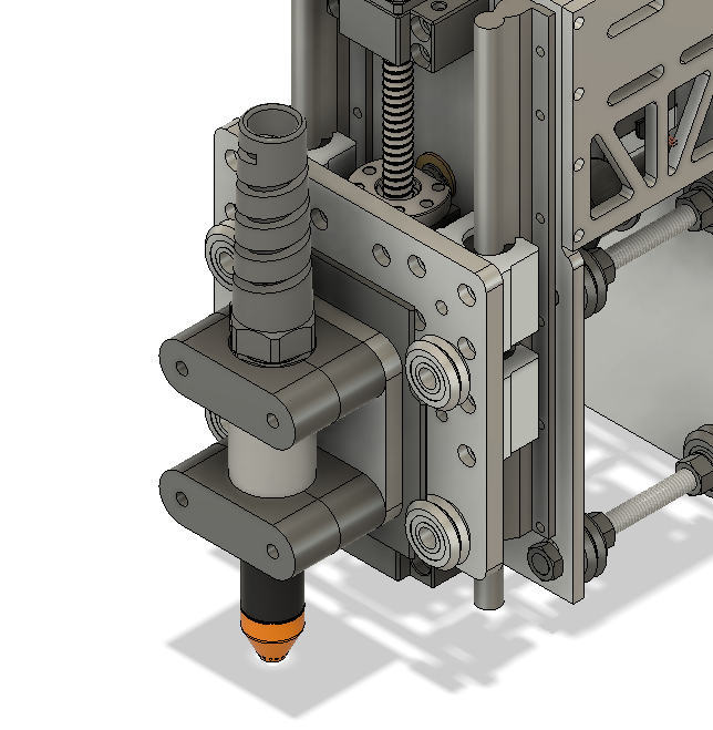
- Z-plate is aluminum, and there are 4/ea V-bearings mounted to it.
- Two of the bearings are on eccentrics so they can tension the slider.
- Float switch mounted on Z-plate, triggered by slider
- Slider is a piece of 1/8" steel plate
- Edges are beveled/rounded and is captured by the V-bearings
- 3 holes drilled in it to locate the bearing balls on the carrier plate
- Microswitch (post-type), NC, triggered by the carrier plate being in place. Switch wires are routed through the Z-plate and up the back.
- Carrier plate is aluminum and has
- 3/ea 3/8" bearing balls pressed in to undersized flat-bottom holes. Holes are just deep enoughso the ball stick out a bit - CAD helps here.
- 3/ea 1/2"x1/4 magnets pressed & epoxied in
Holes in slider can be easily adjusted (chamfer, size) for an appropriate break-away force in all directions. I found that to get a good 'feel', the balls should be buried about 1/3 the diameter of the ball when the magnets are touching the slider plate and slightly chamfered.
The dimensions are also important - the distance between the magnets top to bottom should be fairly short, otherwise you wind up with much stiffer break-away force front to back than rotationally. The torch should have quite a lot of leverage.
Hope it helps.
-Ralph
Attachments:
The following user(s) said Thank You: phillc54, tommylight
Please Log in or Create an account to join the conversation.
- rodw
-

- Offline
- Platinum Member
-
Less
More
- Posts: 11986
- Thank you received: 4082
04 Jan 2022 07:11 #230725
by rodw
Replied by rodw on topic Breakaway torch carrier design
There is another really simple torch breakaway and holder designed by seanp on the plasma spider forum.
It uses 3 ball bearings tig welded from the back that locate into holes on the front pieces. The magnets used then don't really matter.
I am With Andy, Don't use more than 3 location points.
It uses 3 ball bearings tig welded from the back that locate into holes on the front pieces. The magnets used then don't really matter.
I am With Andy, Don't use more than 3 location points.
Please Log in or Create an account to join the conversation.
Moderators: snowgoer540
Time to create page: 0.388 seconds