connecting to laser TTL
- poesel
- Offline
- Senior Member
-

- Posts: 43
- Thank you received: 2
just to make sure I understood that correctly.
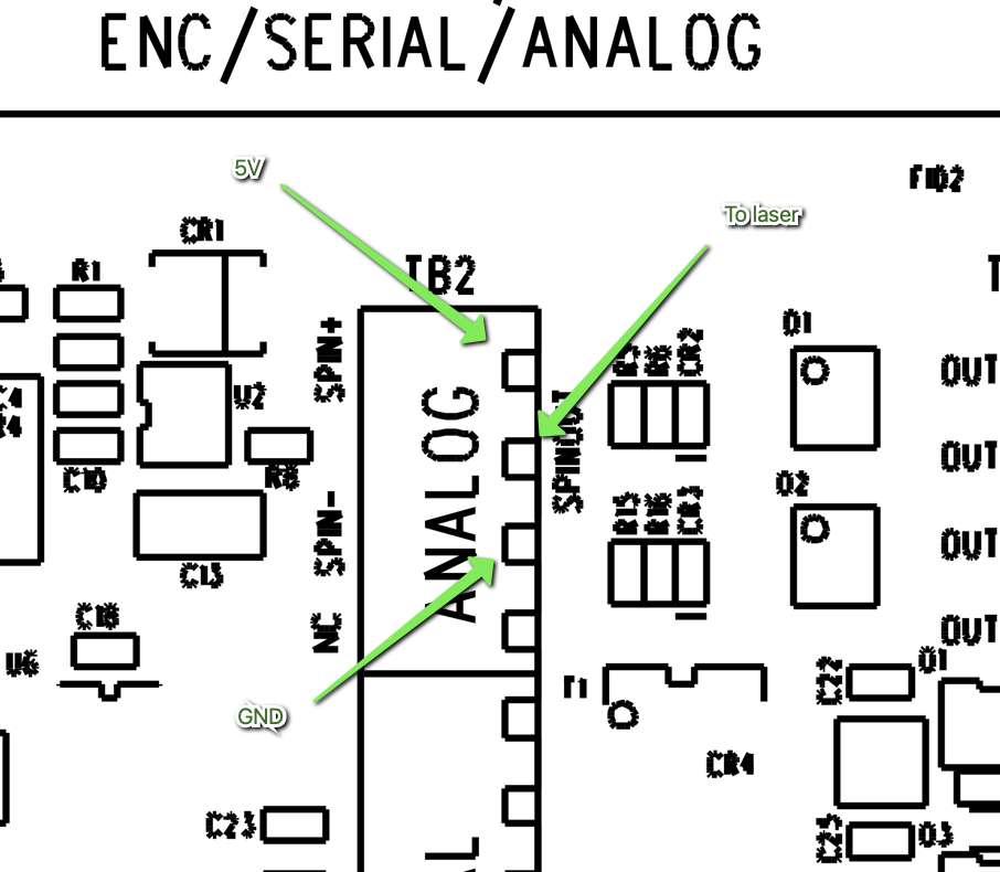
I have a 7i96s and want to connect a laser module which uses a TTL signal to control it. When I connect it like shown below, the M67 command will control the intensity, right? Or do I need to configure something to make that work?
Thanks!
Attachments:
Please Log in or Create an account to join the conversation.
- tommylight
-

- Offline
- Moderator
-

- Posts: 21653
- Thank you received: 7398
analog output = changing voltage from 0 to 5V
PWM = Pulse Width Modulation = pulses with changing duration, so 0 or +5V
-
The correct way would be to flash PWM firmware to Mesa 7i96S included in the downloads from Mesa website (specification tab on the 7i96S page), this will replace the 5'th stepgen with PWM.
If you do need all 5 stepgens, then a cheap BOB connected to Mesa IDC26 header will also work, but i do not know if that also needs flashing or can be used with software PWM.
Please Log in or Create an account to join the conversation.
- poesel
- Offline
- Senior Member
-
- Posts: 43
- Thank you received: 2
The manual of the Atomstack M100 just says 5V TTL. I googled, but did not find any good indication if they meant 5V analog or PWM. Usually (YMMV) more devices work with analog than PWM, so I went that road.
If, from your experience, TTL in this context means PWM, I'll happily take that advice. If you remember, you explained to me yesterday how to flash the second PWM output. So this has already been done.
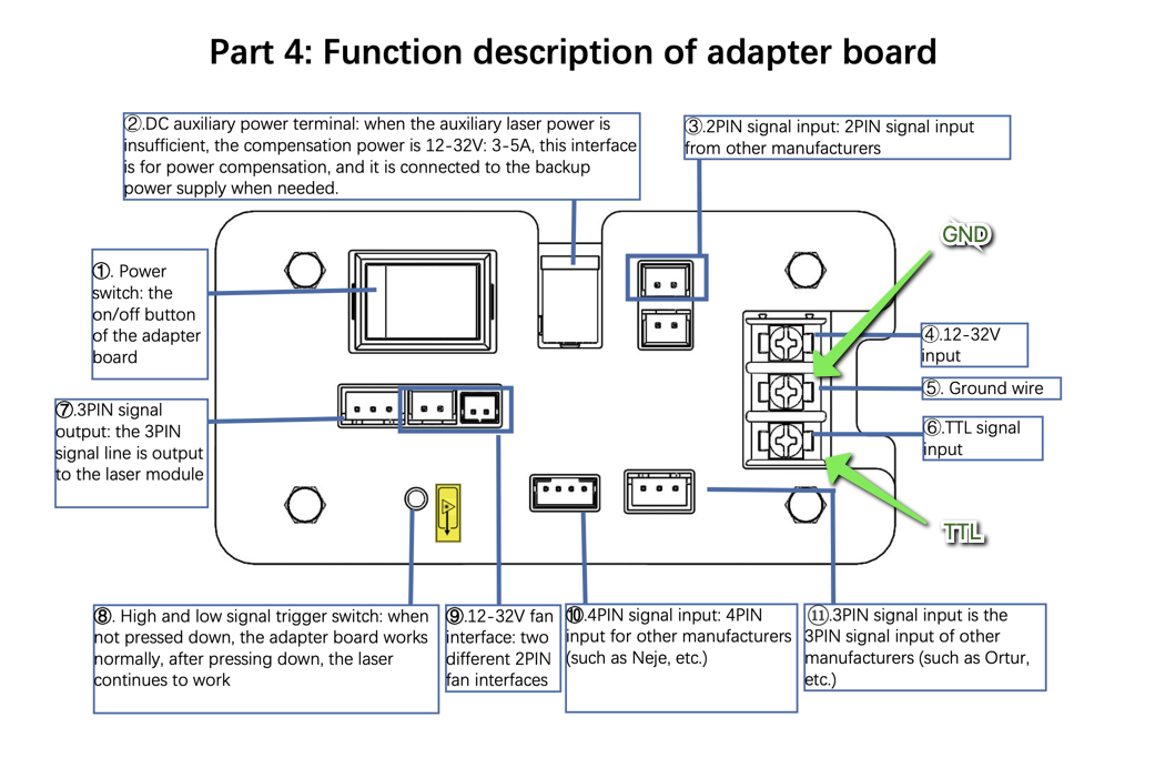
I'll look up in the manual how that needs to be wired and post it here.
Please Log in or Create an account to join the conversation.
- tommylight
-
- Offline
- Moderator
-
- Posts: 21653
- Thank you received: 7398
Yes it does. In this case it means 5V PWM, see below:If, from your experience, TTL in this context means PWM,
The naming TTL has remained from logic IC's back when there were two types of them, the TTL ones (Transistor-Transistor-Logic) and CMOS ( C.... Metal Oxide Semiconductors, damn it cant recall what C stands for),
TTL are 5V powered with +-5% tolerance, and if i recall correctly, "logic 0" was anything under 0.8V and "logic 1" was anything over 2.4V
CMOS were powered by 3V to 9V or more, i think, and "logic 0" was under 33% of the supply voltage and "logic 1" was everything above 66% of the supply voltage.
A bit fuzzy on details, been over 40 years since i used those daily.
Please Log in or Create an account to join the conversation.
- poesel
- Offline
- Senior Member
-
- Posts: 43
- Thank you received: 2
HAL config as per this discussion:
forum.linuxcnc.org/27-driver-boards/5480...and-wiring-for-laser
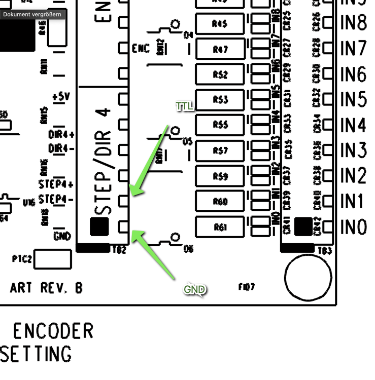
That correct? Thanks.
Attachments:
Please Log in or Create an account to join the conversation.
- poesel
- Offline
- Senior Member
-
- Posts: 43
- Thank you received: 2

This what I added to my .hal:
If you comment in the pwm line (and comment out 'net laser...' you permanently get 1,25V on the output.# invert pwm output
setp hm2_7i96s.0.pwmgen.01.out0.invert_output true
# set output type to PWM
setp hm2_7i96s.0.pwmgen.01.output-type 1 # pwm
# set scale
setp hm2_7i96s.0.pwmgen.01.scale 100 # 100%
# test - this will enable the output and should give about 1,25V
# setp hm2_7i96s.0.pwmgen.01.value 25 # pwm
setp hm2_7i96s.0.pwmgen.01.enable true
# Link PWM output to analog-out 0
net laser-power motion.analog-out-00 => hm2_7i96s.0.pwmgen.01.value
You can also leave it as is, run lcnc and run 'M68 E0 Q25' for the same effect. 'M68 E0 Q0' to turn it off again.
Where I'm not so sure is that the output is permanently enabled and only controlled by M67/M68. I'm going to use Lightburn which uses these M-commands instead of the spindle control. Is that ok?
Please Log in or Create an account to join the conversation.