Probe Basic and Carousel ATC with Geneva and Stepper
- IB_CnC
- Offline
- Senior Member
-

Less
More
- Posts: 42
- Thank you received: 14
26 Apr 2025 09:22 - 26 Apr 2025 09:26 #327079
by IB_CnC
Replied by IB_CnC on topic Probe Basic and Carousel ATC with Geneva and Stepper
About the files, this ATC is quite a specific design for my router.
It was a tricky design with regard to the work area and clearance so I'm not sure this should be a baseline for anyone.
On a typical mill I think the design would be a bit different, same principle but hanging from the top and therefore most of the dimensions probably will change.
But I can share the geneva wheel and drive and how it's setup with Probe Basic, if it works out, no problem if someone wants it.
Happy to give something back to the community.")
It was a tricky design with regard to the work area and clearance so I'm not sure this should be a baseline for anyone.
On a typical mill I think the design would be a bit different, same principle but hanging from the top and therefore most of the dimensions probably will change.
But I can share the geneva wheel and drive and how it's setup with Probe Basic, if it works out, no problem if someone wants it.
Happy to give something back to the community.
Last edit: 26 Apr 2025 09:26 by IB_CnC.
The following user(s) said Thank You: tommylight
Please Log in or Create an account to join the conversation.
- Lcvette
-

- Offline
- Moderator
-

Less
More
- Posts: 1633
- Thank you received: 763
26 Apr 2025 19:08 #327096
by Lcvette
Replied by Lcvette on topic Probe Basic and Carousel ATC with Geneva and Stepper
yes you want to use the geneva pin for the pocket index so its in the locked position. for homing, you could configure it a few ways, but typically i would use the home switch + the index switch so when homed it will be in the locked position of pocket #1. I was planning on using the same dumb motor step generator so please let me know how it works out for you. here is how my home/index is setup on my little atc build:

Attachments:
The following user(s) said Thank You: tommylight, IB_CnC
Please Log in or Create an account to join the conversation.
- IB_CnC
- Offline
- Senior Member
-
Less
More
- Posts: 42
- Thank you received: 14
26 Apr 2025 22:13 #327105
by IB_CnC
Replied by IB_CnC on topic Probe Basic and Carousel ATC with Geneva and Stepper
Thanks, I will try to set it up the same way with both sensors needing to be high for homing.
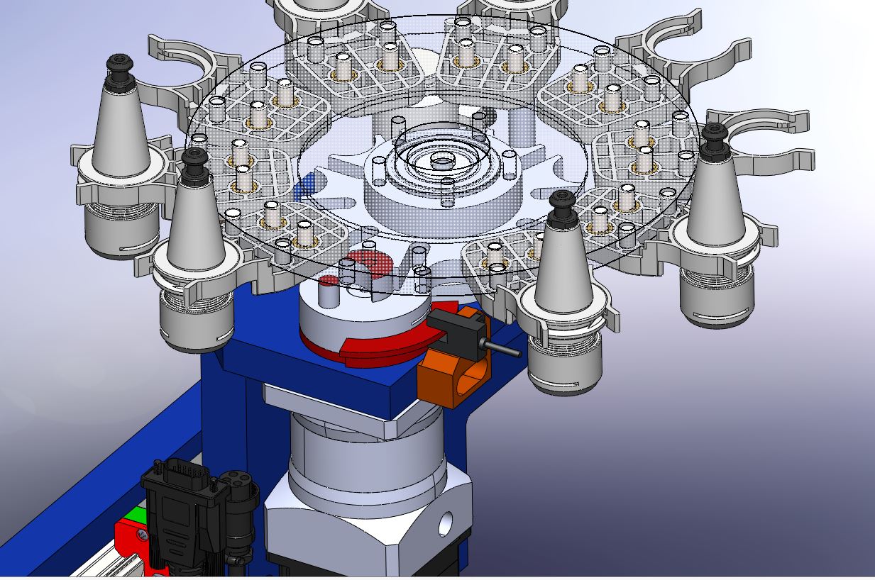
I've made a little setup with optical sensors and for indexing just added a "flag" to my drive wheel.
The homing sensor and flag are below the pocket which is the pickup location for the spindle, as it just happened to be a good spot.


I've made a little setup with optical sensors and for indexing just added a "flag" to my drive wheel.
The homing sensor and flag are below the pocket which is the pickup location for the spindle, as it just happened to be a good spot.
Attachments:
The following user(s) said Thank You: tommylight
Please Log in or Create an account to join the conversation.
- IB_CnC
- Offline
- Senior Member
-
Less
More
- Posts: 42
- Thank you received: 14
30 Apr 2025 02:10 #327324
by IB_CnC
Replied by IB_CnC on topic Probe Basic and Carousel ATC with Geneva and Stepper
Allright!!!! Got the carousel working! Or atleast I can control and home it from the Probe Basic Gui and index it as well, altough I had to struggle a bit.
It's setup with the step generator PCB + 2 relays and two optical sensors.
- Had to figure out how to wire the relays in a way that both carousel directions were switching the "ON/OFF" circuit on the small stepgen PCB, but only 1 direction / relay would close the DIR circuit.
- Had to change 1 parameter in the M13 homing subroutine (P4 to P3), seems to be a typo.
- Had to configure the Index signal with AND2 logic for the M13 homing subroutine, so it looks for both the Index and the Pulse sensors during homing.
- Had some trouble with my NPN optical sensors, because I thought my Mesa 7i84 daughtercard was using NPN, while in reality I needed PNP.


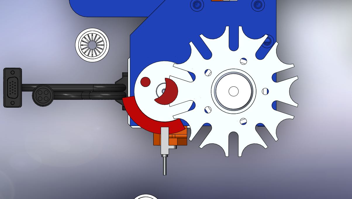
One problem, the drive wheel sensor flag overshoots the sensor by about 25 degrees during homing and index steps.
So when you home or index the carousel, the flag is passing the sensor completely due to deceleration it seems.
The result is if the follow up index movement is in the opposite direction, the flag gets detected after turning back only 25 degrees, with the physical carousel not stepping an index position, while the software does register +1 index pocket.
Not sure I can change decel with the stepgen PCB setup.
Two options to solve I think:
1- Create a longer flag on the drivewheel, so more like a lobe, which allows some more margin
2- Replace the drive wheel index sensor for a pulse flag on each pocket. The decel timing will give the geneva drive pin enough time to move out of the slot and properly engage.
Will try option 1 first, as I can just print a new disc with a longer flag.
It's setup with the step generator PCB + 2 relays and two optical sensors.
- Had to figure out how to wire the relays in a way that both carousel directions were switching the "ON/OFF" circuit on the small stepgen PCB, but only 1 direction / relay would close the DIR circuit.
- Had to change 1 parameter in the M13 homing subroutine (P4 to P3), seems to be a typo.
- Had to configure the Index signal with AND2 logic for the M13 homing subroutine, so it looks for both the Index and the Pulse sensors during homing.
- Had some trouble with my NPN optical sensors, because I thought my Mesa 7i84 daughtercard was using NPN, while in reality I needed PNP.
One problem, the drive wheel sensor flag overshoots the sensor by about 25 degrees during homing and index steps.
So when you home or index the carousel, the flag is passing the sensor completely due to deceleration it seems.
The result is if the follow up index movement is in the opposite direction, the flag gets detected after turning back only 25 degrees, with the physical carousel not stepping an index position, while the software does register +1 index pocket.
Not sure I can change decel with the stepgen PCB setup.
Two options to solve I think:
1- Create a longer flag on the drivewheel, so more like a lobe, which allows some more margin
2- Replace the drive wheel index sensor for a pulse flag on each pocket. The decel timing will give the geneva drive pin enough time to move out of the slot and properly engage.
Will try option 1 first, as I can just print a new disc with a longer flag.
Please Log in or Create an account to join the conversation.
- IB_CnC
- Offline
- Senior Member
-
Less
More
- Posts: 42
- Thank you received: 14
30 Apr 2025 02:18 #327325
by IB_CnC
Replied by IB_CnC on topic Probe Basic and Carousel ATC with Geneva and Stepper
Anyways, the basic functionality is working.
I still have to wire up and map the ATC spindle PNP sensors to detect clamping / unclamping and the sensors for the out position of the Carousel cylinder, before I can try to run a toolchange. But that should work out fine.
Once everything is working, I'll do a writeup how it's configured.
I still have to wire up and map the ATC spindle PNP sensors to detect clamping / unclamping and the sensors for the out position of the Carousel cylinder, before I can try to run a toolchange. But that should work out fine.
Once everything is working, I'll do a writeup how it's configured.
Please Log in or Create an account to join the conversation.
- IB_CnC
- Offline
- Senior Member
-
Less
More
- Posts: 42
- Thank you received: 14
30 Apr 2025 07:23 - 30 Apr 2025 07:24 #327329
by IB_CnC
Replied by IB_CnC on topic Probe Basic and Carousel ATC with Geneva and Stepper
I think this will solve the issue:
Will try today!
Will try today!
Attachments:
Last edit: 30 Apr 2025 07:24 by IB_CnC.
Please Log in or Create an account to join the conversation.
- IB_CnC
- Offline
- Senior Member
-
Less
More
- Posts: 42
- Thank you received: 14
30 Apr 2025 12:32 - 30 Apr 2025 12:35 #327337
by IB_CnC
Replied by IB_CnC on topic Probe Basic and Carousel ATC with Geneva and Stepper
Basic homing and CW/CW rotation indexing working fine now!
Altough it responds with a small delay (due to the stepgen PCB)
Some vids:
Next step is mapping and wiring the other sensors!
Altough it responds with a small delay (due to the stepgen PCB)
Some vids:
Next step is mapping and wiring the other sensors!
Last edit: 30 Apr 2025 12:35 by IB_CnC.
The following user(s) said Thank You: tommylight
Please Log in or Create an account to join the conversation.
- tommylight
-

- Away
- Moderator
-
Less
More
- Posts: 21712
- Thank you received: 7418
30 Apr 2025 14:16 #327345
by tommylight
Replied by tommylight on topic Probe Basic and Carousel ATC with Geneva and Stepper
Any idea why such a long delay between pressing a button and the actual move?
Please Log in or Create an account to join the conversation.
- IB_CnC
- Offline
- Senior Member
-
Less
More
- Posts: 42
- Thank you received: 14
30 Apr 2025 14:51 - 30 Apr 2025 15:20 #327352
by IB_CnC
Replied by IB_CnC on topic Probe Basic and Carousel ATC with Geneva and Stepper
I think it has to do with the 10 bucks stepgen PCB, it also happened before I removed the physical pushbuttons and soldered wires to it.
It's not a big issue, but would be nice if it responds faster.
I have to double check the stepper driver dip switch settings.
If no luck i think it might be possible to put a relay on the EN+/- wire, between the PCB and the stepper driver and just leave the PCB ON constantly, only changing direction by switching the DIR and activating the stepper driver via the Enabled signal.
That could solve it, will test later on. It would send out pulse signal constantly, but can't think of a reason why that would be an issue.
Last edit: 30 Apr 2025 15:20 by IB_CnC.
The following user(s) said Thank You: tommylight
Please Log in or Create an account to join the conversation.
- IB_CnC
- Offline
- Senior Member
-
Less
More
- Posts: 42
- Thank you received: 14
30 Apr 2025 18:19 - 30 Apr 2025 18:34 #327375
by IB_CnC
Replied by IB_CnC on topic Probe Basic and Carousel ATC with Geneva and Stepper
Found out why it delays when switching on.
The stepper driver (HBS57) is disabled by a 3.5V signal to the ENA+/- ports.
When you enable the driver by pulling the voltage signal (directly or via the pulse gen PCB), apparently it takes a bit of time for the driver to react.
This also happens when using a different 5V powersupply.
It does react instantly when you re-apply the 3.5V to the ENA+- ports, instantly stopping the motion.
If I can invert the ENA (Enabled) signal in the driver software, I can switch the opposite by relay to apply a voltage to enable the driver instead of disabling it. But I could get an issue stopping the driver in time if I do that.
I have to figure out how to connect to the driver, never done that before.
Last edit: 30 Apr 2025 18:34 by IB_CnC.
Please Log in or Create an account to join the conversation.
Moderators: KCJ, Lcvette
Time to create page: 0.431 seconds