- User Interfaces
- Other User Interfaces
- QtPyVCP
- problems with Y-Axis, elliptic deviations after several changes -Probe Basic V.5
problems with Y-Axis, elliptic deviations after several changes -Probe Basic V.5
- Muftijaja
- Offline
- Premium Member
-

Less
More
- Posts: 102
- Thank you received: 4
18 Nov 2025 21:48 #338659
by Muftijaja
problems with Y-Axis, elliptic deviations after several changes -Probe Basic V.5 was created by Muftijaja
Hello community!
I have a Mesa 7i76e running, the wiring is correct except for the alarm loop. Using a Lenovo ThinkCentre M910q with i7 4-core, 256/GB NVMe SSD, i7 16GB RAM WLAN Intel Core i7-6700T 4x 2.80 - 3.60GHz with Linuxcnc 2.9.4, Probe Basic V.5 on Debian 12. No latency problems.
Once again, I'm here with a big problem. My DIY milling machine (1000x500x220 with aluminum profile frame, 20mm HGR, 1605 ball screws, 3 axes, 2x OMC Stpperonline 400W integrated servo, 1x JMC CL Stepper 3.5Nm, set 2000 steps/rev) is now mechanically finally assembled. I also got a lot of help from this forum in setting up LinuxCNC, eliminating latency problems and spindle control problems, but now I have a milling problem that I can't solve.
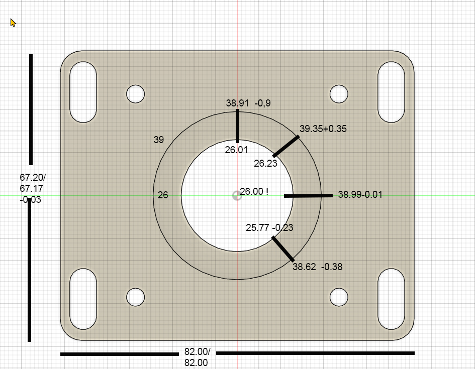
I have milled several test parts with drill holes, 2 circular pockets, and a rectangular outer contour, and have noticed that my circular pockets are becoming elliptical. The deviations in Y are approximately +0.35 mm at 45° and approximately -0.38 mm at 135°. The X values for the rectangular contour are perfect to within 0.01 mm in X and 0.09 mm in Y, X I consider to be acceptable, but Y is over tolerance. However, the circular movements contain deviations I cannot tolerate. I will show you a photo of the last test piece. After each individual test part, I made changes to rule out certain things.
The first change was to replace a simple Chinese C7 ball screw with a ground C5 spindle with double nuts. This reduced the originally even higher values by almost half. However, the deviations described above remained. After the next test part, I replaced the 400 W servo with a 3.5 Nm JMC CL stepper motor. The results remained almost the same. As a final attempt, a few days ago I replaced the spindle's fixed bearing with a new one, with 7002AC angular contact bearings in an O-arrangement with a 1 mm spacer ring between the outer rings. I inspected the previous fixed bearing and found no faults. There was a 1mm spacer also and the O arrangement was the same. I had also taken measurements at the spindle end earlier and actually and found no backlash.
Yesterday, moving away from mechanical faults, I noticed a difference in the motor definitions for the X and Y axes in the .ini file. The Ferror and min_Ferror points differed by one decimal place. X was set to 0.1 and 0.01, while the Y axis was set to 1.0 and 0.1. After I corrected this difference, the motor on the Y axis went into alarm mode after a few position changes.
What could be the reason for this? How can it be that one motor runs perfectly with much lower tolerance values, while the other quickly goes into alarm mode with less load? The motor in question has the same power supply and is certainly less demanding in terms of starting currents than the servo on the X-axis. With the higher tolerance values, the Y motor runs without alarm, but has these deviations. Are these tolerance values in the .ini file responsible for these deviations?
The mechanics of the Y and Z axes are flawless, as checked with a dial gauge, and the repeat accuracy is also very good, less than one hundredth.
Do you have any ideas about this? Where can I look further?
Thanks for your time and hints
I have a Mesa 7i76e running, the wiring is correct except for the alarm loop. Using a Lenovo ThinkCentre M910q with i7 4-core, 256/GB NVMe SSD, i7 16GB RAM WLAN Intel Core i7-6700T 4x 2.80 - 3.60GHz with Linuxcnc 2.9.4, Probe Basic V.5 on Debian 12. No latency problems.
Once again, I'm here with a big problem. My DIY milling machine (1000x500x220 with aluminum profile frame, 20mm HGR, 1605 ball screws, 3 axes, 2x OMC Stpperonline 400W integrated servo, 1x JMC CL Stepper 3.5Nm, set 2000 steps/rev) is now mechanically finally assembled. I also got a lot of help from this forum in setting up LinuxCNC, eliminating latency problems and spindle control problems, but now I have a milling problem that I can't solve.
I have milled several test parts with drill holes, 2 circular pockets, and a rectangular outer contour, and have noticed that my circular pockets are becoming elliptical. The deviations in Y are approximately +0.35 mm at 45° and approximately -0.38 mm at 135°. The X values for the rectangular contour are perfect to within 0.01 mm in X and 0.09 mm in Y, X I consider to be acceptable, but Y is over tolerance. However, the circular movements contain deviations I cannot tolerate. I will show you a photo of the last test piece. After each individual test part, I made changes to rule out certain things.
The first change was to replace a simple Chinese C7 ball screw with a ground C5 spindle with double nuts. This reduced the originally even higher values by almost half. However, the deviations described above remained. After the next test part, I replaced the 400 W servo with a 3.5 Nm JMC CL stepper motor. The results remained almost the same. As a final attempt, a few days ago I replaced the spindle's fixed bearing with a new one, with 7002AC angular contact bearings in an O-arrangement with a 1 mm spacer ring between the outer rings. I inspected the previous fixed bearing and found no faults. There was a 1mm spacer also and the O arrangement was the same. I had also taken measurements at the spindle end earlier and actually and found no backlash.
Yesterday, moving away from mechanical faults, I noticed a difference in the motor definitions for the X and Y axes in the .ini file. The Ferror and min_Ferror points differed by one decimal place. X was set to 0.1 and 0.01, while the Y axis was set to 1.0 and 0.1. After I corrected this difference, the motor on the Y axis went into alarm mode after a few position changes.
What could be the reason for this? How can it be that one motor runs perfectly with much lower tolerance values, while the other quickly goes into alarm mode with less load? The motor in question has the same power supply and is certainly less demanding in terms of starting currents than the servo on the X-axis. With the higher tolerance values, the Y motor runs without alarm, but has these deviations. Are these tolerance values in the .ini file responsible for these deviations?
The mechanics of the Y and Z axes are flawless, as checked with a dial gauge, and the repeat accuracy is also very good, less than one hundredth.
Do you have any ideas about this? Where can I look further?
Thanks for your time and hints
Attachments:
Please Log in or Create an account to join the conversation.
- Lcvette
-

- Offline
- Moderator
-

Less
More
- Posts: 1624
- Thank you received: 755
18 Nov 2025 23:32 #338667
by Lcvette
Replied by Lcvette on topic problems with Y-Axis, elliptic deviations after several changes -Probe Basic V.5
Mwchanical issue maybe or backlash of your acis settings are correct.
The following user(s) said Thank You: Muftijaja
Please Log in or Create an account to join the conversation.
- Hakan
- Offline
- Platinum Member
-

Less
More
- Posts: 1317
- Thank you received: 453
18 Nov 2025 23:39 - 18 Nov 2025 23:39 #338668
by Hakan
Replied by Hakan on topic problems with Y-Axis, elliptic deviations after several changes -Probe Basic V.5
About the following error, there is no real position feedback, only position feedback from stepgen.
That P=500 is ok for your 2 ms servo-period?
That P=500 is ok for your 2 ms servo-period?
Last edit: 18 Nov 2025 23:39 by Hakan.
The following user(s) said Thank You: Muftijaja
Please Log in or Create an account to join the conversation.
- tommylight
-

- Away
- Moderator
-
Less
More
- Posts: 21638
- Thank you received: 7393
18 Nov 2025 23:40 #338669
by tommylight
Replied by tommylight on topic problems with Y-Axis, elliptic deviations after several changes -Probe Basic V.5
What material is being milled?
You wont like this, but that can very easily be mechanical flex from aluminium parts, there is reason why cast metal is used for mills.
Still, a quick test for that is to make the same part much slower and check if the error is smaller.
You wont like this, but that can very easily be mechanical flex from aluminium parts, there is reason why cast metal is used for mills.
Still, a quick test for that is to make the same part much slower and check if the error is smaller.
The following user(s) said Thank You: Muftijaja
Please Log in or Create an account to join the conversation.
- Muftijaja
- Offline
- Premium Member
-
Less
More
- Posts: 102
- Thank you received: 4
19 Nov 2025 01:56 - 19 Nov 2025 13:10 #338684
by Muftijaja
Replied by Muftijaja on topic problems with Y-Axis, elliptic deviations after several changes -Probe Basic V.5
Thanks for your reply, Lcvette!
Okay, I think I have a (relative") )rigid machine for a hobby CNC. All critical plates are made of 20mm 5083 aluminum, heavy profiles filled with cement, an 80x160mm filled portal profile, 20mm HGR guides. A good standard for a 1000x500 machine. I aligned everything using angles and a dial gauge. I placed a dial gauge on the end of the Y ball screw, which shows only 1/100 mm of backlash. Using a spring balance, I pulled with 20 kg on the spindle in the X and Y directions, with a maximum deflection of 0.06 mm, in the X less in the Y direction. I think the mechanics are OK, as this deviation of almost 0.5 mm cannot be explained.
)rigid machine for a hobby CNC. All critical plates are made of 20mm 5083 aluminum, heavy profiles filled with cement, an 80x160mm filled portal profile, 20mm HGR guides. A good standard for a 1000x500 machine. I aligned everything using angles and a dial gauge. I placed a dial gauge on the end of the Y ball screw, which shows only 1/100 mm of backlash. Using a spring balance, I pulled with 20 kg on the spindle in the X and Y directions, with a maximum deflection of 0.06 mm, in the X less in the Y direction. I think the mechanics are OK, as this deviation of almost 0.5 mm cannot be explained.
Ok, You say, my settings are correct. What is the reason for motor alarms at the reduction of FERROR from 1.0 to 0.1 and MIN.FERROR from 0.1 to 0.01?
Okay, I think I have a (relative
)rigid machine for a hobby CNC. All critical plates are made of 20mm 5083 aluminum, heavy profiles filled with cement, an 80x160mm filled portal profile, 20mm HGR guides. A good standard for a 1000x500 machine. I aligned everything using angles and a dial gauge. I placed a dial gauge on the end of the Y ball screw, which shows only 1/100 mm of backlash. Using a spring balance, I pulled with 20 kg on the spindle in the X and Y directions, with a maximum deflection of 0.06 mm, in the X less in the Y direction. I think the mechanics are OK, as this deviation of almost 0.5 mm cannot be explained.Ok, You say, my settings are correct. What is the reason for motor alarms at the reduction of FERROR from 1.0 to 0.1 and MIN.FERROR from 0.1 to 0.01?
Last edit: 19 Nov 2025 13:10 by Muftijaja.
Please Log in or Create an account to join the conversation.
- Muftijaja
- Offline
- Premium Member
-
Less
More
- Posts: 102
- Thank you received: 4
19 Nov 2025 02:16 - 19 Nov 2025 02:25 #338691
by Muftijaja
Replied by Muftijaja on topic problems with Y-Axis, elliptic deviations after several changes -Probe Basic V.5
Hakan, thanks for your reply! Yes the 500 were the result of another contribution and the servo thread setting at 2 million.
See forum.linuxcnc.org/42-deutsch/55139-moto...4-7-5-m-min?start=20
There are other hints for FF1 and FF2 in the motor settings, even though there is no real feedback loop. I don't understand this in depth, but I follow those experts as tommylight and PCW.
See forum.linuxcnc.org/42-deutsch/55139-moto...4-7-5-m-min?start=20
There are other hints for FF1 and FF2 in the motor settings, even though there is no real feedback loop. I don't understand this in depth, but I follow those experts as tommylight and PCW.
Last edit: 19 Nov 2025 02:25 by Muftijaja.
Please Log in or Create an account to join the conversation.
- Muftijaja
- Offline
- Premium Member
-
Less
More
- Posts: 102
- Thank you received: 4
19 Nov 2025 02:24 #338692
by Muftijaja
Replied by Muftijaja on topic problems with Y-Axis, elliptic deviations after several changes -Probe Basic V.5
Thanks for your answer! My tests are in aluminum EN-AW 5083. That is my target material.
Yes I know that a really stiff machine should be made of steel or cast, but I have bult what I could.
Yes I know that a really stiff machine should be made of steel or cast, but I have bult what I could.
Please Log in or Create an account to join the conversation.
- Hakan
- Offline
- Platinum Member
-
Less
More
- Posts: 1317
- Thank you received: 453
19 Nov 2025 04:51 #338702
by Hakan
Replied by Hakan on topic problems with Y-Axis, elliptic deviations after several changes -Probe Basic V.5
Ok 500 is fine. I knew it is 1000 for 1 ms but not how it scaled.
I was looking for a reason for the following error.
Since the feedback comes from the step generator and not the actual machine,
it seems to me the step generator is to blame.
You get following error even when running in air, right?
Basically linuxcnc, or perhaps the step generator, generates the wrong tool path in Y.
Unfottunately I don't know how to fix it.
The following user(s) said Thank You: Muftijaja
Please Log in or Create an account to join the conversation.
- Muftijaja
- Offline
- Premium Member
-
Less
More
- Posts: 102
- Thank you received: 4
19 Nov 2025 13:07 #338715
by Muftijaja
Replied by Muftijaja on topic problems with Y-Axis, elliptic deviations after several changes -Probe Basic V.5
Thanks, Hakan. Yes, yesterday I cancelled my Air-path as I could see the motor is going into alarm. I don't know if there is a following error as a reason for this, Iwill pot my serial connection to the motor today to read the logs and reproduce the error.
What I can say, mechanics are not the reason, because - what I changed just before were the entries at FERROR and MIN.FERROR to 0.1 and 0.01, exactly what is in the x-axis, which is running fine with these settings.
What I can say, mechanics are not the reason, because - what I changed just before were the entries at FERROR and MIN.FERROR to 0.1 and 0.01, exactly what is in the x-axis, which is running fine with these settings.
Please Log in or Create an account to join the conversation.
- Lcvette
-
- Offline
- Moderator
-
Less
More
- Posts: 1624
- Thank you received: 755
19 Nov 2025 14:39 - 19 Nov 2025 14:55 #338723
by Lcvette
Replied by Lcvette on topic problems with Y-Axis, elliptic deviations after several changes -Probe Basic V.5
are getting reported when from driver's or linuxcnc? What is the axis drive type? Bal screws or rack or belt? Edit: Nevermind saw c5 screws
Your fixed bearing arrangement isn't ideal. Ac bearings should be matched sets requiring no intermediary spacers for preload. Adjusting correct preload with spacers between the bearing set is incredibly variable and difficult. It is for certain an easy way to destroy bearings as I've done it in the past and turned the balls to crumbled bits. That said I don't think that's enough for your deviation, just a suggestion for future improvement.
Feed forward is used with PID tuning for servos and a feed back loop, if your using simple steppers this shouldn't need an adjustment over the ff = 1
Last edit: 19 Nov 2025 14:55 by Lcvette.
Please Log in or Create an account to join the conversation.
Moderators: KCJ, Lcvette
- User Interfaces
- Other User Interfaces
- QtPyVCP
- problems with Y-Axis, elliptic deviations after several changes -Probe Basic V.5
Time to create page: 0.387 seconds