Very small 4 axis mill for cutting plastic materials
- tommylight
-
 Topic Author
- Offline
- Moderator
-

Less
More
- Posts: 21691
- Thank you received: 7414
06 Oct 2025 12:39 #335916
by tommylight
Very small 4 axis mill for cutting plastic materials was created by tommylight
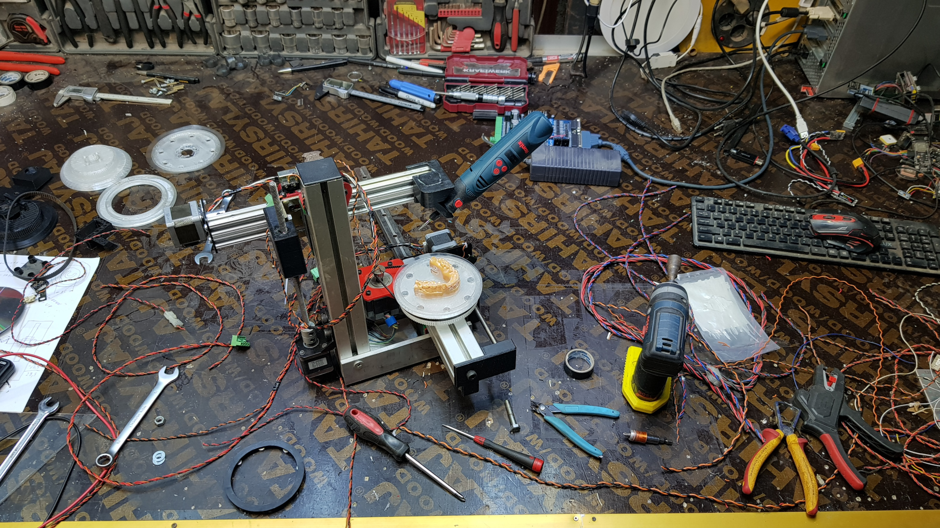
This is what i was doing last few days, a very small 4 axis cnc machine for cutting some kind of plastic material for clear teeth aligners, machine is fully finished (except a box for electronics and cutting the protruding HGR25 rail to size).
-The machine kinematics are simple XYZC.
-The mill bit is angled at 35 degrees from table, can be changed to 90 or any other angle
-the C axis can spin freely both directions and has a home switch, with limits at+-99999 in ini only
-table/C axis is designed in FreeCAD and 3D printed, with 120 tooth HTD3 pulley included
Below is what i have to work with:
-the file generated from their software is a simple text file (.pts extension) with values for 3 axis, BUT has no axis assignments at all, only numbers, so with a bit of help from Gemini a filter was made to open the .pts file and assign axis letters together with Feed rate and M2, all that works fine
-also made a filter that adds the fourth axis that also seems to work, but not as required by this task, C does move small amounts to account for the tool cutting angle, but this requires rotating the C axis 360 degrees for a full job
-that job is always a single cut line, always same location of the material, always indexed on C, material shape does change but never significantly
-that is the only job this machine will do.
-
The machines used for this are 4 or 5 axis, always, and they use that same file type with 3 axis values, so the kinematics or CAM must do the required changes/modifications to path, and this is where i am stuck, so any ideas are welcomed.
Attachments:
The following user(s) said Thank You: partec
Please Log in or Create an account to join the conversation.
- tommylight
-
Topic Author
- Offline
- Moderator
-
Less
More
- Posts: 21691
- Thank you received: 7414
07 Oct 2025 01:09 - 07 Oct 2025 01:14 #335969
by tommylight
Replied by tommylight on topic Very small 4 axis mill for cutting plastic materials
Did anyone notice there is a question at the end? ")
-
Some random info running through my noggin :
-the rotational axis should do a full 360 degree to finish this
-the tool should remain always roughly normal to the teeth/cut plane
-i do not think this needs switchable kinematics
-pretty sure this needs TCP as the cut line is always 1mm under the material (also 1mm thick roughly)
-having a look through the included TRT configs right now ... well after i get back from the shop (nicotine level low), went to bed at 1AM got up at 2:10AM, way to much stuff going on last 3-4 days compounded by family health issues, but getting better so far.
Attached files in pts and gcode formats, compressed, the gcode has Y and Z axis values changed to reflect table orientation.
Last edit: 07 Oct 2025 01:14 by tommylight. Reason: more info
The following user(s) said Thank You: partec
Please Log in or Create an account to join the conversation.
- partec
- Offline
- Elite Member
-

Less
More
- Posts: 173
- Thank you received: 27
07 Oct 2025 10:06 #335989
by partec
Replied by partec on topic Very small 4 axis mill for cutting plastic materials
I saw the question and you have now attached exactly the relevant files. Thanks, I'll be happy to think about it!
The following user(s) said Thank You: tommylight
Please Log in or Create an account to join the conversation.
- tommylight
-
Topic Author
- Offline
- Moderator
-
Less
More
- Posts: 21691
- Thank you received: 7414
07 Oct 2025 15:31 #336018
by tommylight
Replied by tommylight on topic Very small 4 axis mill for cutting plastic materials
Thank you very much.
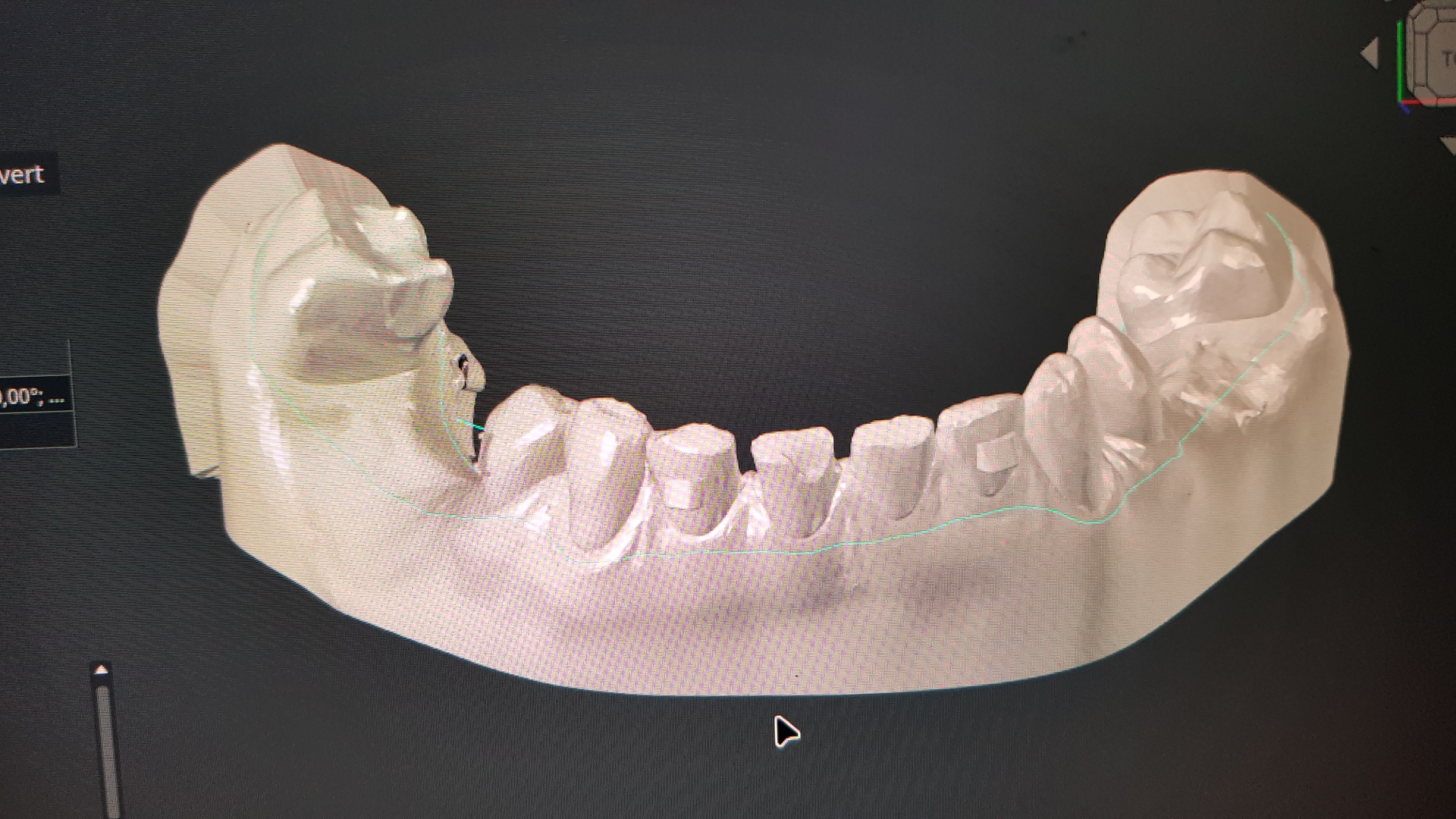
Attached are both filters for LinuxCNC, the normal 3 axis and the generated 4th axis noted in the file names inside the zip file, also require adding these two lines to the ini fileorAnd another try at explaining things, badly as usual, the attached 3D image has the blueish-green cut line that is the actual gcode, so the tool should be horizontally positioned to cut the line
Attached are both filters for LinuxCNC, the normal 3 axis and the generated 4th axis noted in the file names inside the zip file, also require adding these two lines to the ini file
PROGRAM_EXTENSION = .pts values
pts = ./LinuxCNC_pts_filter.pyPROGRAM_EXTENSION = .pts values
pts = ./LinuxCNC_pts_filter_4_axis.py
The following user(s) said Thank You: partec
Please Log in or Create an account to join the conversation.
- partec
- Offline
- Elite Member
-
Less
More
- Posts: 173
- Thank you received: 27
07 Oct 2025 16:18 #336025
by partec
Replied by partec on topic Very small 4 axis mill for cutting plastic materials
I do believe that a simplified milling procedure can be implemented.
The C-axis must be adjusted so that the milling spindle is approximately perpendicular to the cutting contour in every small section.
A fully converted X-Y-Z-C point file is required.
You write:
-pretty sure this needs TCP as the cut line is always 1mm under the material (also 1mm thick roughly)
What exactly do you mean by that TCP?
You also write:
-having a look through the included TRT configs
What exactly do you mean by that TRT?
Surely you also have an envelope file (stp or similar)?
The following user(s) said Thank You: tommylight
Please Log in or Create an account to join the conversation.
- tommylight
-
Topic Author
- Offline
- Moderator
-
Less
More
- Posts: 21691
- Thank you received: 7414
07 Oct 2025 19:59 #336049
by tommylight
On the LinuxCNC configuration selecotr, go to sample configurations>sim>axis>vismach>5axis>table-rotary-tilting and choose one of the two configs to run.
Again, thank you very much.
Replied by tommylight on topic Very small 4 axis mill for cutting plastic materials
TCP = Tool Center Piont, the kinematics that keep the tool positioned in the same place no matter how the axis/joints are moving (might not be the best explanation, i know)What exactly do you mean by that TCP?
LinuxCNC comes with several 5 axis TCP-TRT simulated configs that also have a Vismach visualization screen/window where the machine can be seen moving, makes things much easier to test.What exactly do you mean by that TRT?
On the LinuxCNC configuration selecotr, go to sample configurations>sim>axis>vismach>5axis>table-rotary-tilting and choose one of the two configs to run.
Yes, an STL 3D model as shown in the picture above.Surely you also have an envelope file (stp or similar)?
Again, thank you very much.
The following user(s) said Thank You: partec
Please Log in or Create an account to join the conversation.
- partec
- Offline
- Elite Member
-
Less
More
- Posts: 173
- Thank you received: 27
07 Oct 2025 22:38 #336065
by partec
Replied by partec on topic Very small 4 axis mill for cutting plastic materials
Thank you for these very interesting explanations.
I've barely familiarized myself with these special LinuxCNC capabilities until now, but I certainly sense their great potential.
In my ever-loved RHINO, I primarily try to find analytical geometric solutions directly, for example, an X-Y-Z-C-Points.ngc where the spatial position of the envelope shape is precisely used as the basis for the cutting contour.
The method you mentioned in the forum, e.g. according to github.com/FreddieHong19/Open5x, could also be used as an idea for creating such a suitable X-Y-Z-C-Punkte.ngc with Grasshopper.
Please Log in or Create an account to join the conversation.
- tommylight
-
Topic Author
- Offline
- Moderator
-
Less
More
- Posts: 21691
- Thank you received: 7414
10 Jul 2026 01:56 #347648
by tommylight
Replied by tommylight on topic Very small 4 axis mill for cutting plastic materials
This machine is still waiting for the files it has to use, so still with me, and of course i had to play a bit with it tonight as i do have some sample files to play with that may or may not end up what we use.
I might have chased the wrong rabbit when i built this, so a bit of TCP exercise is in order...if i get the chance.
Any advice that might save me time, please do chime in.
Thank you.
I might have chased the wrong rabbit when i built this, so a bit of TCP exercise is in order...if i get the chance.
Any advice that might save me time, please do chime in.
Thank you.
Please Log in or Create an account to join the conversation.
- Aciera
-

- Offline
- Administrator
-

Less
More
- Posts: 4735
- Thank you received: 2122
10 Jul 2026 07:46 #347653
by Aciera
Replied by Aciera on topic Very small 4 axis mill for cutting plastic materials
So, the .pts files contain a path on the surface of a 3d model as consecutive 3d points and you are trying to post process this to create 4axis (xyzc) gcode where the c axis keeps the tool perpendicular to the model surface.
Seems you are basically trying to use a python filter script to do what a CAM and post prosessor would usually do.
You could use dx and dy from the pts file to calculate the tool orientation angle in the xy-plane (ie the c axis value) that keeps the tool perpendicular to the path segment. In order to keep the tool positioned on the work piece while the c-axis moves you need TCP kinematics.
The 1mm tool path offset could possibly be achieved by simply using a 2mm bull nose bit (depends on the required detail resolution of course).
If you need to use smaller tools then you would likely need to calculate new xyz coordinates to compensate for the 1mm offset and tool radius compensation.
Of course, the proper and easy way to do this would be to use a CAM
Please Log in or Create an account to join the conversation.
Time to create page: 0.219 seconds