Step or velocity control for servo gantry
- PCW
-

- Offline
- Moderator
-

- Posts: 17927
- Thank you received: 5251
#********************
[AXIS_0]
TYPE = LINEAR
HOME = 100.0
FERROR = 1.0
MIN_FERROR = 1.0
MAX_VELOCITY = 83.3333333333
MAX_ACCELERATION = 10000.0
# The values below should be 25% larger than MAX_VELOCITY and MAX_ACCELERATION
# If using BACKLASH compensation STEPGEN_MAXACCEL should be 100% larger.
STEPGEN_MAXVEL = 104.2
STEPGEN_MAXACCEL = 12500.0
P = 1.0
I = 0.0
D = 0.0
FF0 = 0.0
FF1 = 1.0
FF2 = 0.0
BIAS = 0.0
DEADBAND = 0.025
MAX_OUTPUT = 10.0
This will limit you to 10 mm/s
Please Log in or Create an account to join the conversation.
- crisiacuf
- Offline
- Junior Member
-

- Posts: 22
- Thank you received: 0
After lots of head smashing ...
")
thank you for your help guys.
I am still in step/dir and seems to be working
# Axis X
#********************
[AXIS_0]
TYPE = LINEAR
HOME = 100.0
FERROR = 5.0
MIN_FERROR = 5.0
MAX_VELOCITY = 250.0
MAX_ACCELERATION = 2500.0
# The values below should be 25% larger than MAX_VELOCITY and MAX_ACCELERATION
# If using BACKLASH compensation STEPGEN_MAXACCEL should be 100% larger.
STEPGEN_MAXVEL = 0
STEPGEN_MAXACCEL = 0
P = 0.0
I = 0.0
D = 0.0
FF0 = 0.0
FF1 = 1.0
FF2 = 0.0
BIAS = 0.0
DEADBAND = 0.025
MAX_OUTPUT = 0.0
ENCODER_SCALE = 200.0
# these are in nanoseconds
DIRSETUP = 1000
DIRHOLD = 1000
STEPLEN = 1000
STEPSPACE = 1000
STEP_SCALE = 400.0
MIN_LIMIT = -0.0
MAX_LIMIT = 1200.0
HOME_OFFSET = 0.000000
HOME_SEARCH_VEL = -0.050000
HOME_LATCH_VEL = -0.016667
HOME_FINAL_VEL = 1.666667
HOME_USE_INDEX = NO
HOME_IGNORE_LIMITS = YES
Please Log in or Create an account to join the conversation.
- DaBit
- Offline
- Elite Member
-

- Posts: 203
- Thank you received: 19
I really think that switching the servodrives to positioning mode (I suppose they can do that, right?) is the best solution.
Please Log in or Create an account to join the conversation.
- crisiacuf
- Offline
- Junior Member
-
- Posts: 22
- Thank you received: 0
Drivers are in position mode with step/did input and auto tune.
Please Log in or Create an account to join the conversation.
- DaBit
- Offline
- Elite Member
-
- Posts: 203
- Thank you received: 19
setp   hm2_5i25.0.stepgen.00.control-type     1
..
..
# ---closedloop stepper signals---
..
net x-output                             => hm2_5i25.0.stepgen.00.velocity-cmd
..
I wonder why you don't use positioning mode then?
Please Log in or Create an account to join the conversation.
- crisiacuf
- Offline
- Junior Member
-
- Posts: 22
- Thank you received: 0
Looking in your HAL file:
setp   hm2_5i25.0.stepgen.00.control-type     1
..
..
# ---closedloop stepper signals---
..
net x-output                             => hm2_5i25.0.stepgen.00.velocity-cmd
..
I wonder why you don't use positioning mode then?
Funny, ha?!?
I guess that's why it works! I tested the control type 0, position-cmd, now, but it does not work. It oscillates VIOLENTLY(NOT "violently happy").
.HAL:
#*******************
# AXIS X
#*******************
setp pid.x.Pgain [AXIS_0]P
setp pid.x.Igain [AXIS_0]I
setp pid.x.Dgain [AXIS_0]D
setp pid.x.bias [AXIS_0]BIAS
setp pid.x.FF0 [AXIS_0]FF0
setp pid.x.FF1 [AXIS_0]FF1
setp pid.x.FF2 [AXIS_0]FF2
setp pid.x.deadband [AXIS_0]DEADBAND
setp pid.x.maxoutput [AXIS_0]MAX_OUTPUT
net x-index-enable <=> pid.x.index-enable
net x-enable => pid.x.enable
net x-output => pid.x.output
net x-pos-cmd => pid.x.command
net x-vel-fb => pid.x.feedback-deriv
net x-pos-fb => pid.x.feedback
# Step Gen signals/setup
setp hm2_5i25.0.stepgen.00.dirsetup [AXIS_0]DIRSETUP
setp hm2_5i25.0.stepgen.00.dirhold [AXIS_0]DIRHOLD
setp hm2_5i25.0.stepgen.00.steplen [AXIS_0]STEPLEN
setp hm2_5i25.0.stepgen.00.stepspace [AXIS_0]STEPSPACE
setp hm2_5i25.0.stepgen.00.position-scale [AXIS_0]STEP_SCALE
setp hm2_5i25.0.stepgen.00.step_type 0
setp hm2_5i25.0.stepgen.00.control-type 0
setp hm2_5i25.0.stepgen.00.maxaccel [AXIS_0]STEPGEN_MAXACCEL
setp hm2_5i25.0.stepgen.00.maxvel [AXIS_0]STEPGEN_MAXVEL
# ---closedloop stepper signals---
net x-pos-cmd axis.0.motor-pos-cmd
net x-output => hm2_5i25.0.stepgen.00.position-cmd
net x-enable axis.0.amp-enable-out => hm2_5i25.0.stepgen.00.enable
and ini:
#********************
# Axis X
#********************
[AXIS_0]
TYPE = LINEAR
HOME = 100.0
FERROR = 5.0
MIN_FERROR = 100.0
MAX_VELOCITY = 100.0
MAX_ACCELERATION = 2500.0
# The values below should be 25% larger than MAX_VELOCITY and MAX_ACCELERATION
# If using BACKLASH compensation STEPGEN_MAXACCEL should be 100% larger.
STEPGEN_MAXVEL = 0
STEPGEN_MAXACCEL = 0
P = 1.0
I = 0.0
D = 0.0
FF0 = 0.0
FF1 = 1.0
FF2 = 0.0
BIAS = 0.0
DEADBAND = 0.025
MAX_OUTPUT = 0.0
ENCODER_SCALE = 200.0
# these are in nanoseconds
DIRSETUP = 1000
DIRHOLD = 1000
STEPLEN = 1000
STEPSPACE = 1000
STEP_SCALE = 400.0
MIN_LIMIT = -0.0
MAX_LIMIT = 1200.0
HOME_OFFSET = 0.000000
HOME_SEARCH_VEL = -0.050000
HOME_LATCH_VEL = -0.016667
HOME_FINAL_VEL = 1.666667
HOME_USE_INDEX = NO
HOME_IGNORE_LIMITS = YES
I probably have to RTFM more closely, I know, but my particular situation is not covered in detail anywhere. As long as I know.
I somehow use a mix now.
What I got now seems to work. I tested the axis in jog mode and I got around 0.005mm precision, measured with a 0.001mm precision instrument.
I use the internal PID in the servos(which probably is well tuned) and probably just use the hal and linear scales as a watchdog, and visual information.
For example when the ferror is above xx the machine will come to a halt.
Please Log in or Create an account to join the conversation.
- DaBit
- Offline
- Elite Member
-
- Posts: 203
- Thank you received: 19
That it doesn't work with the HAL/INI you posted doesn't surprise me.
You want the servo to do the positioning, and add a small correction for any error made in that process by the linear drive system with the scale.
Thus, you want is to feed (axis.N.motor-pos-cmd PLUS scale correction) to the servo (hm2_5i25.0.stepgen.00.position-cmd). This is not what you do in your HAL file.
You can accomplish this in 2 ways:
1) Use a sum2 to sum the motor-pos-cmd and pid.x.output together.
2) Set the pid.x.FF0 coefficient to 1.0, which does basically the same. FF0 is zero order forward, thus setting it to 1.0 just adds the command to the output.
I chose method 1) because summing externally makes the PID output simply the correction needed. That allows me to limit pid.x.output to a low value of only 0.1..0.2mm, and seeing the correction separate from the position command makes it easier for my limited brain to understand what is going on during debugging.
Once again: ignore the servo PID's: in your case they are in the drive.
With the servo in positioning mode, do this first:
-> pid.x.FF0 1.0, the rest zero.
Now you have the scale loop in place, but it is disabled. The position command enters the PID, gets copied to the output, and is fed to the stepgen position-cmd.
Try it, and do whatever tuning is necessary to the drive and STEP_SCALE to get things as accurate as possible. Let the servodrive do the heavy lifting. If it doesn't work there is something wrong in your HAL connections.
Then increase pid.x.Igain. No P, no D, no FF1. Only I.
Now the position is corrected by the scale. The higher the I, the quicker the correction.
I probably have to RTFM more closely, I know, but my particular situation is not covered in detail anywhere. As long as I know.
That's because almost nobody does it. When you are building a professonal machine it makes more sense to use C3-class or better ballscrews, preloaded nuts and decent bearing blocks instead of adding a 'slow' linear scale that is a fairly fragile component also.
I want C3 screws and bearing blocks with $400 worth of bearing in them too, but I am not willing to pay the money for my hobby machine. So I chose Chinese screws costing less than threaded rod bought locally and added a sub-$100 linear scale to correct for the inherent error in these screws (they are not even C7 class).
I tested the axis in jog mode and I got around 0.005mm precision
At various CNC forums I see people post wonderfuly accurate positioning when the axis is stationary. That does not say much; at that condition there is no mechanical load on the axis and it has infinite time to reach the desired position. Just add a bit of Igain, and you will reach your goal of a very accurate stationary position.
When milling things change. The machine base distorts, disturbances are injected in the positioning loops, etcetera. A set of coefficients that work well when 'stationary' might not work so well when actually milling.
This is also why I do not use P in the scale loop. It tends to cause an overreaction and torque ripple on my system. Easy to test: move the axis, and hit it with a hammer to inject a disturbance

I-only tends to act as a lowpass filter, correcting for error buildup only.
Please Log in or Create an account to join the conversation.
- crisiacuf@yahoo.com
- Offline
- New Member
-

- Posts: 8
- Thank you received: 0
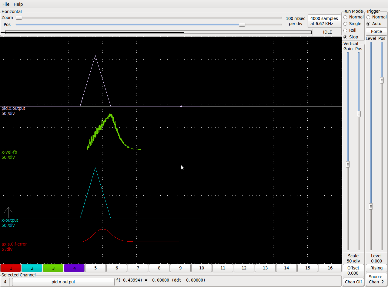
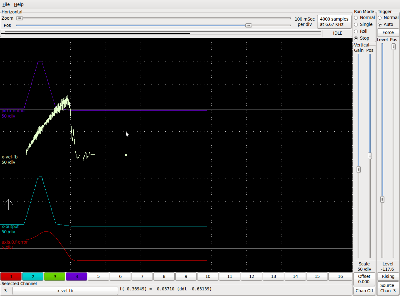
I tried the partial PID loop but couldn't decrease the ferror much.
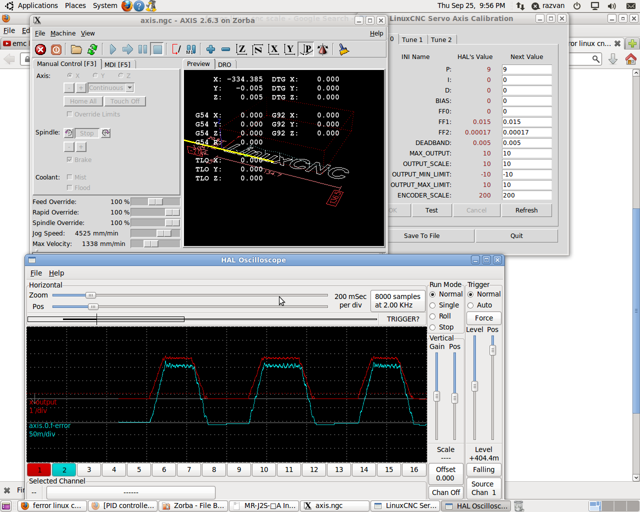
I changed the command system to velocity and I am now using a 5i25+7i77+7i78(not used for now) mesa setup.
My melservo MRJ2S's are conected to the +/-10V analog drive of the 7i77.
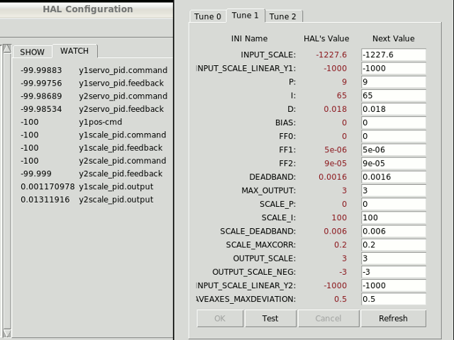
Without canceling the auto tuning in the servos I got a ferror of about 0,2mm @ 4500mm/min on the X axis. I only used P, FF1 and FF2(I spent a couple of hours trying to adjust I and D with no succes).
I don't know if it's better to completely disable the servos auto tuning but I will try soon.
What ferror would be acceptable at this speed for metal work?
Now I need to setup the gantrykins for the dual Y joints.
I'm considering using the ICECOLD(DaBit) gantry config files but don't really understand what's in them for now(although I read the related post).
Any sugestions or guidelines?
Please Log in or Create an account to join the conversation.
- DaBit
- Offline
- Elite Member
-
- Posts: 203
- Thank you received: 19
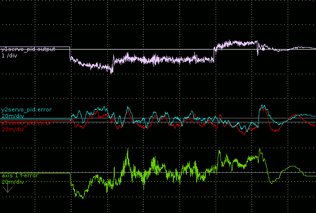
This is the two Y-axes running the gantry in 'pure machine torture' mode: 1,1G acceleration, 200mm/sec. Accelerating ~150kg of steel and stone so fast feels like a giant is thumping the machine with a big sledgehammer. But it does exaggerate the effects of FF1/FF2.
My X axis is a bit more sloppy than Y.
X does 819 pulses/mm on the motor encoder, 200 pulses/mm on the linear encoder. Y does 1229 pulses/mm on the motor encoders, 1000 pulses/mm on the linear encoder and the 400W servos on Y are far more dynamic than that 750W beast on the X.
How are your servos setup? Position mode? Velocity mode? Torque mode?
Please Log in or Create an account to join the conversation.
- crisiacuf@yahoo.com
- Offline
- New Member
-
- Posts: 8
- Thank you received: 0
Please Log in or Create an account to join the conversation.