Step or velocity control for servo gantry
- DaBit
- Offline
- Elite Member
-

Less
More
- Posts: 203
- Thank you received: 19
29 Sep 2014 22:40 #51662
by DaBit
Replied by DaBit on topic Step or velocity control for servo gantry
- Setup all the scalings so that units make sense. If PID output is 10, then the motor should turn 10 revs/sec. This is not necessary from the computer point of view, but it helps the poor guy watching halscope and entering parameters a lot.
- Assuming the PID does position in, velocity out: set FF0 to 0.0, FF1 to 1.0, FF2 to 0.0, P to some small value (1.0 or so), I and D to 0.0.
- Make sure you set the 'error-previous-target' pin of the PID controller to 1, otherwise you have a velocity-dependant following error.
- Set FERROR and MAX_FERROR to high values. Make them 1000 or so.
- Do some jogs, watch over/undershoots on f-error at the beginning and ending of the jog. Try to compensate them by adding a little FF2. Compensate a linear increase/decrease in f-error by adjusting FF1 until the f-error is approximately flat during cruise.
- Now increase P until the system becomes unstable, then backoff.
This should give you very decent tracking already. Try to arrive at this point first.
Please Log in or Create an account to join the conversation.
- crisiacuf
- Offline
- Junior Member
-

Less
More
- Posts: 22
- Thank you received: 0
30 Sep 2014 23:23 #51693
by crisiacuf
Replied by crisiacuf on topic Step or velocity control for servo gantry
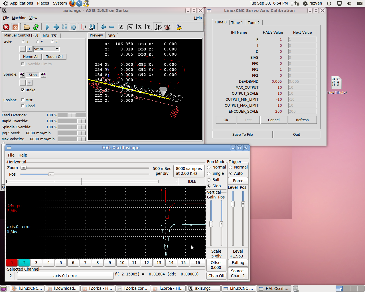
It seems I have the PID setup corectly but when I make FF1 = 1 this happens:
Here is my HAL for X axis:
What linuxcnc version do you have? My head hurts trying to compare my hal with yours")
Here is my HAL for X axis:
#*******************
#  AXIS X
#*******************

setp   pid.x.Pgain     [AXIS_0]P
setp   pid.x.Igain     [AXIS_0]I
setp   pid.x.Dgain     [AXIS_0]D
setp   pid.x.bias      [AXIS_0]BIAS
setp   pid.x.FF0       [AXIS_0]FF0
setp   pid.x.FF1       [AXIS_0]FF1
setp   pid.x.FF2       [AXIS_0]FF2
setp   pid.x.deadband  [AXIS_0]DEADBAND
setp   pid.x.maxoutput [AXIS_0]MAX_OUTPUT

net x-index-enable  <=>  pid.x.index-enable
net x-enable       => pid.x.enable
net x-output       => pid.x.output
net x-pos-cmd      => pid.x.command
net x-vel-fb       => pid.x.feedback-deriv
net x-pos-fb       => pid.x.feedback

#my insert
setp pid.x.error-previous-target 1

# ---PWM Generator signals/setup---

setp   hm2_5i25.0.7i77.0.1.analogout0-scalemax  [AXIS_0]OUTPUT_SCALE
setp   hm2_5i25.0.7i77.0.1.analogout0-minlim    [AXIS_0]OUTPUT_MIN_LIMIT
setp   hm2_5i25.0.7i77.0.1.analogout0-maxlim    [AXIS_0]OUTPUT_MAX_LIMIT

net x-output                             => hm2_5i25.0.7i77.0.1.analogout0
net x-pos-cmd    axis.0.motor-pos-cmd
net x-enable     axis.0.amp-enable-out
# enable _all_ sserial pwmgens
net x-enable   hm2_5i25.0.7i77.0.1.analogena

# ---Encoder feedback signals/setup---

setp    hm2_5i25.0.encoder.00.counter-mode 0
setp    hm2_5i25.0.encoder.00.filter 1
setp    hm2_5i25.0.encoder.00.index-invert 0
setp    hm2_5i25.0.encoder.00.index-mask 0
setp    hm2_5i25.0.encoder.00.index-mask-invert 0
setp    hm2_5i25.0.encoder.00.scale  [AXIS_0]ENCODER_SCALE

net x-pos-fb               <=  hm2_5i25.0.encoder.00.position
net x-vel-fb               <=  hm2_5i25.0.encoder.00.velocity
net x-pos-fb               =>  axis.0.motor-pos-fb
net x-index-enable    axis.0.index-enable  <=>  hm2_5i25.0.encoder.00.index-enable
net x-pos-rawcounts        <=  hm2_5i25.0.encoder.00.rawcounts

# ---setup home / limit switch signals---

net home-x     =>  axis.0.home-sw-in
net min-x     =>  axis.0.neg-lim-sw-in
net max-x     =>  axis.0.pos-lim-sw-in
What linuxcnc version do you have? My head hurts trying to compare my hal with yours
Please Log in or Create an account to join the conversation.
- PCW
-

- Offline
- Moderator
-

Less
More
- Posts: 17927
- Thank you received: 5251
30 Sep 2014 23:29 #51694
by PCW
Replied by PCW on topic Step or velocity control for servo gantry
FF1 =1
only makes sense if your output scale is in machine units per second at full scale
So for analog velocity mode drives the output scale (= scalemax and maxlim and -minlim for 7I77)
= how fast your axis move in mm/s at 10V velocity command
only makes sense if your output scale is in machine units per second at full scale
So for analog velocity mode drives the output scale (= scalemax and maxlim and -minlim for 7I77)
= how fast your axis move in mm/s at 10V velocity command
Please Log in or Create an account to join the conversation.
- DaBit
- Offline
- Elite Member
-
Less
More
- Posts: 203
- Thank you received: 19
01 Oct 2014 04:41 - 01 Oct 2014 04:47 #51700
by DaBit
Replied by DaBit on topic Step or velocity control for servo gantry
What PCW said. And you seem to be using only the scale as position feedback. This is going to be pretty hard and will result in a sluggish loop at best since you only have 200 pulses per millimeter to work with and any form of nonlinear mechanics will bite hard. And since metal is not infinitely stiff and nothing can move without play the nonlinearity is there. Maybe small, maybe not, but it is there.
On my mill the encoder on the motor and lead of the screw is the primary positioning method. The scale is only used to correct residual errors and it does so only 'slowly'.
Forget about the scale at this point and make the servo work flawless without it first. Thinking about adding the scale to the positioning loop before that makes no sense.
I am running 2.7.0~pre BTW, but that does not matter. It would work the same with 2.5 or 2.6, especially if you set pid.x.error-previous-target=1
Last edit: 01 Oct 2014 04:47 by DaBit.
Please Log in or Create an account to join the conversation.
- crisiacuf@yahoo.com
- Offline
- New Member
-

Less
More
- Posts: 8
- Thank you received: 0
01 Oct 2014 15:34 - 01 Oct 2014 15:35 #51703
by crisiacuf@yahoo.com
Replied by crisiacuf@yahoo.com on topic Step or velocity control for servo gantry
My axis moves at 25 mm/s @ 1V measured
My encoder velocity corectly shows 25.xxxx @ 1V
Max speed is 250mm/s @10V
My encoder velocity corectly shows 25.xxxx @ 1V
Max speed is 250mm/s @10V
Last edit: 01 Oct 2014 15:35 by crisiacuf@yahoo.com.
Please Log in or Create an account to join the conversation.
- DaBit
- Offline
- Elite Member
-
Less
More
- Posts: 203
- Thank you received: 19
01 Oct 2014 15:51 #51704
by DaBit
Replied by DaBit on topic Step or velocity control for servo gantry
Then make:
[AXIS_0]OUTPUT_SCALE -> 250
[AXIS_0]OUTPUT_MIN_LIMIT -> -250
[AXIS_0]OUTPUT_MAX_LIMIT -> 250
and make sure that the axis moves with 10mm/sec in one direction when you set hm2_5i25.0.7i77.0.1.analogout0 to 10 and 10mm/sc in the other direction when you set hm2_5i25.0.7i77.0.1.analogout0 to -10
Did you also connect the rotary encoder outputs of your servo drive to the 7i77? If not you should do so. Once again: forget about the scale for now, and get that servo running properly first.
Please Log in or Create an account to join the conversation.
- crisiacuf@yahoo.com
- Offline
- New Member
-
Less
More
- Posts: 8
- Thank you received: 0
01 Oct 2014 15:55 - 01 Oct 2014 15:55 #51705
by crisiacuf@yahoo.com
Replied by crisiacuf@yahoo.com on topic Step or velocity control for servo gantry
Got it!
Why you use the rotary encoder was my next question but you answered it allready.
What other mesa board beside 7i77 do you use for the rest of the encoders? XYYZ takes 8 encoder inputs and 7i77 hax only 6.
Why you use the rotary encoder was my next question but you answered it allready.
What other mesa board beside 7i77 do you use for the rest of the encoders? XYYZ takes 8 encoder inputs and 7i77 hax only 6.
Last edit: 01 Oct 2014 15:55 by crisiacuf@yahoo.com.
Please Log in or Create an account to join the conversation.
- DaBit
- Offline
- Elite Member
-
Less
More
- Posts: 203
- Thank you received: 19
01 Oct 2014 16:41 - 01 Oct 2014 16:46 #51706
by DaBit
Replied by DaBit on topic Step or velocity control for servo gantry
My Z-axis is driven by a stepper, so I need only 7 encoders (Z only needs 1 encoder-input for the scale).
I loaded the 7i77+7i76 firmware on the 6i25 and used a small breadboard with 3x SN75176 and some extra electronics on it for the stepper channels and extra RS422-capable encoder channels.
With 7i77+7i76 firmware on a 5i25/6i25 you can do up to 8 encoders. More than that and you probably need custom firmware, but it can be done. I tried building custom firmware once, and it worked. But so far I have no need for it.
I am sure that it is possible to buy another piece of Mesa hardware for the extra encoder inputs (7i48 maybe?), but I'll let PCW elaborate on that.
Last edit: 01 Oct 2014 16:46 by DaBit.
Please Log in or Create an account to join the conversation.
- alan_3301
- Offline
- Premium Member
-

Less
More
- Posts: 136
- Thank you received: 22
01 Oct 2014 18:59 #51710
by alan_3301
shouldnt this be pid.0.Pgain?
in the docs <loopnum> is a number, don't know if a letter works?
Ignore if I am wrong.
Replied by alan_3301 on topic Step or velocity control for servo gantry
setp pid.x.Pgain [AXIS_0]P
shouldnt this be pid.0.Pgain?
in the docs <loopnum> is a number, don't know if a letter works?
Ignore if I am wrong.
Please Log in or Create an account to join the conversation.
- PCW
-
- Offline
- Moderator
-
Less
More
- Posts: 17927
- Thank you received: 5251
02 Oct 2014 03:28 - 02 Oct 2014 03:29 #51717
by PCW
Replied by PCW on topic Step or velocity control for servo gantry
To add additional differential encoders, I would use either a 7I85 or 7I85S.
Either of these options will add 4 encoder channels that can be TTL or differential
The 7I85S may be more suitable if you anticipate needing any step/dir or PWM outputs
Either of these options will add 4 encoder channels that can be TTL or differential
The 7I85S may be more suitable if you anticipate needing any step/dir or PWM outputs
Last edit: 02 Oct 2014 03:29 by PCW.
Please Log in or Create an account to join the conversation.
Time to create page: 3.554 seconds