
gearchange
- anfänger
-

- Offline
- Platinum Member
-

Less
More
- Posts: 636
- Thank you received: 260
26 Jan 2021 06:59 #196605
by anfänger
Replied by anfänger on topic gearchange
Damn, still a lot to learn.
Thanks!
Thanks!
Please Log in or Create an account to join the conversation.
- andypugh
-

- Offline
- Moderator
-

Less
More
- Posts: 19898
- Thank you received: 4654
26 Jan 2021 23:49 #196683
by andypugh
Compared to another forum I spend my time on, that gearbox looks great
It will clean up, I think.
Here is an example of a gearbox that is now driving a lorry around Dudley:
hmvf.co.uk/topic/30968-1914-dennis-lorry...mment&comment=383985
(Though, to be fair, other than one gear being very badly worn, the real problem there is the horribly corroded gearbox case, with one mounting leg completely gone.
Replied by andypugh on topic gearchange
but at home i got a shock after a deeper lock
Compared to another forum I spend my time on, that gearbox looks great
It will clean up, I think.
Here is an example of a gearbox that is now driving a lorry around Dudley:
hmvf.co.uk/topic/30968-1914-dennis-lorry...mment&comment=383985
(Though, to be fair, other than one gear being very badly worn, the real problem there is the horribly corroded gearbox case, with one mounting leg completely gone.
Please Log in or Create an account to join the conversation.
- COFHAL
- Offline
- Platinum Member
-
Less
More
- Posts: 461
- Thank you received: 62
26 Jul 2026 18:19 - 26 Jul 2026 18:21 #348077
by COFHAL
Replied by COFHAL on topic gearchange
I have a lathe with a 9-speed gearbox that is manually selected. The motor is always running at its maximum speed of 1360 RPM, and the speed is manually changed using the gears. I'm using your gearchange component, which supports up to 32 speeds. I've already implemented the logic to select each speed. In each range, I'll control the speed with a VFD between the lowest value of the previous speed and the maximum, according to the original lathe's speed chart. For example, the first speed is 36 RPM, the second is 90 RPM, and the third is 155 RPM. Then, in the first speed, the spindle would rotate between 0 and 36 RPM, and the motor would rotate between 0 and 1360 RPM. In the second speed, between 36 RPM and 90 RPM, the motor would rotate in that gear between the speed that the gear provides, resulting in 36 RPM and 90 RPM at the spindle. This pattern is repeated for the other speeds. My question regarding this component is how to adjust the scale on each device; I don't know if it's always done relative to the first one or relative to the previous one.
Last edit: 26 Jul 2026 18:21 by COFHAL.
Please Log in or Create an account to join the conversation.
- COFHAL
- Offline
- Platinum Member
-
Less
More
- Posts: 461
- Thank you received: 62
10 Aug 2026 15:15 - 10 Aug 2026 16:47 #348632
by COFHAL
Replied by COFHAL on topic gearchange
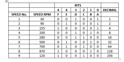
I'm automating a parallel lathe with a 9-speed gearbox selected manually using two levers, each with 3 positions: lever 1 has positions A, B, and C, and lever 2 has positions D, E, and F. The possible combinations are as follows: Direction changes are achieved by activating two electromagnetic clutches.This gives me the following truth table: I'm using the gearchange component for up to 32 speeds created by Andy Pugh, which can be used in this case. The first problem I encountered was creating the logic to detect these combinations, as I needed to detect the positions of the 6 switches I'm going to install to control the lever positions. Of the 6 bits, two will always be true. The component I found and was able to use was LUT5, but the problem is that it's only valid for 5 bits, and there are 3 combinations where bit 5 is one. Therefore, for these 3 combinations, in addition to LUT5, I had to use an additional AND2 gate to detect them.I read on the forum that for some automatic gear shifters, like the Maho MH400E, they created a component with an array that detects each gear by the switch positions.I also used the generic mux component to identify which gear was selected using a number between 1 and 9. Since it's 9 bits, it gave me a combination of 512, of which I only used 9 so that the mux output was a number between 1 and 9.I don't know if there's another way to detect the switch combination for the two levers.I've attached my HAL file to detect each lever position so I can send the correct speed to the VFD.

Last edit: 10 Aug 2026 16:47 by COFHAL.
Please Log in or Create an account to join the conversation.
- rodw
-

- Offline
- Platinum Member
-
Less
More
- Posts: 12156
- Thank you received: 4149
11 Aug 2026 13:12 #348650
by rodw
Replied by rodw on topic gearchange
Sometimes a custom component simplifies your hal file. Here is my solution for a similar problem where there are two belts each with 4 positions. But because it's not possible for both belts to use the same position, it comes down to the same problem you have. For the ratios, I just ran the spindle on each belt combination and read the actual rpm with a cheap laser tacho and did some maths. But I did not have levers, and made a panel for qtdragon which Chris "borrowed" for the qtdragon docs.
github.com/rodw-au/vmnmillqt/blob/main/scalebelts.comp
github.com/rodw-au/vmnmillqt/blob/main/scalebelts.comp
Please Log in or Create an account to join the conversation.
- andypugh
-
- Offline
- Moderator
-
Less
More
- Posts: 19898
- Thank you received: 4654
09 Sep 2026 12:24 #349489
by andypugh
Replied by andypugh on topic gearchange
Rather than LUT5 look at using a match_8 for each gear.
Alternatively, a mux_generic with 6 bit inputs could provide the gear number, or a pair of them could provide the speed limits.
Your HAL file would only need to define inputs for the valid gear positions, not for all 64 possibilities.
Alternatively, a mux_generic with 6 bit inputs could provide the gear number, or a pair of them could provide the speed limits.
loadrt mux_generic config="ff64,ff64,ff64" names="gear,max,min"Please Log in or Create an account to join the conversation.
Time to create page: 0.102 seconds