Retrofitting a 1986 Maho MH400E
- drimaropoylos
- Offline
- Elite Member
-

Less
More
- Posts: 265
- Thank you received: 40
04 Oct 2017 08:02 #99903
by drimaropoylos
Replied by drimaropoylos on topic Retrofitting a 1986 Maho MH400E
G code M41,M42,M43,M44 for gear selection is one way.
Please Log in or Create an account to join the conversation.
- RotarySMP
-
 Topic Author
- Offline
- Platinum Member
-

Less
More
- Posts: 1627
- Thank you received: 595
04 Oct 2017 12:12 #99915
by RotarySMP
Replied by RotarySMP on topic Retrofitting a 1986 Maho MH400E
Have you decided where are you going to put the spindle encoder? I doubt that assumed spindle RPM based on VFD sensed rpm divided by gear ratio will be sufficiently accurate to enable the Z axis to snyc for rigid tapping. There must be a fair amount of backlash through that gearbox. I haven't pulled the hydraulic cover off the head yet, so I don't know how much space is in there for an encoder.
I do not want to implement non standard G codes for gear changes. That would then require more programming for the CAM software to output the required codes. A LinuxCNC internal solution would be much more elegant. Have you seen the HAL component Andy Pugh wrote for this? db1981 has also offered his code for the MAHO gearbox control, so hopefully we can solve this such that the G-code program can contain any S speed, and the MAHO selects the closest.
If we go to all the work of getting the mid and back gear controlled, the input gear must be a minor incremental extra effort,I hope")
Mark
I do not want to implement non standard G codes for gear changes. That would then require more programming for the CAM software to output the required codes. A LinuxCNC internal solution would be much more elegant. Have you seen the HAL component Andy Pugh wrote for this? db1981 has also offered his code for the MAHO gearbox control, so hopefully we can solve this such that the G-code program can contain any S speed, and the MAHO selects the closest.
If we go to all the work of getting the mid and back gear controlled, the input gear must be a minor incremental extra effort,I hope
Mark
Please Log in or Create an account to join the conversation.
- drimaropoylos
- Offline
- Elite Member
-
Less
More
- Posts: 265
- Thank you received: 40
04 Oct 2017 12:41 - 04 Oct 2017 13:12 #99918
by drimaropoylos
Replied by drimaropoylos on topic Retrofitting a 1986 Maho MH400E
When I install the vfd then I will deactivate the input gear. For start I will operate the full gear box.
The Mitsubishi vfd is sensored, I need the encoder at the motor to operate in vector control mode. i need to solve the grounding of the motor shaft, and installation of the encoder to make the transition to vfd. The backlash in the gears is one problem and the slip of the belt is another, but any diy encoder in the head will have lower resolution then the backlash. the most of the backlash you feel when rotate the spindle by hand, is not in the gears, but the break on the motor has some play. I hope the remaining backlash in the gears is acceptable for rigid taping, if not than I will examine other options.
Any help is welcome, have any links?
John
Last edit: 04 Oct 2017 13:12 by drimaropoylos.
Please Log in or Create an account to join the conversation.
- RotarySMP
-
Topic Author
- Offline
- Platinum Member
-
Less
More
- Posts: 1627
- Thank you received: 595
04 Oct 2017 17:13 - 04 Oct 2017 21:36 #99928
by RotarySMP
Replied by RotarySMP on topic Retrofitting a 1986 Maho MH400E
This is te thread where Andy Pugh posted his code for a HAL component to control a four speed gearbox.
forum.linuxcnc.org/38-general-linuxcnc-q...control?limitstart=0
He also added this earlier in this thread:
forum.linuxcnc.org/12-milling/33035-retr...e?limitstart=0#96020
db1981 wrote earlier in this thread that he has written a HAL component to control a MAHO gearbox
forum.linuxcnc.org/12-milling/33035-retr...h400e?start=10#96074
He will share it, but just wanted to clean up the code a little.
Will you remove the spindle brake and add the encoder there? With a breaking resister on the VFD the mechanical brake is probabaly unnecessary.
Mark
Last edit: 04 Oct 2017 21:36 by RotarySMP.
Please Log in or Create an account to join the conversation.
- drimaropoylos
- Offline
- Elite Member
-
Less
More
- Posts: 265
- Thank you received: 40
04 Oct 2017 20:06 #99938
by drimaropoylos
Replied by drimaropoylos on topic Retrofitting a 1986 Maho MH400E
The best is to keep the break for safety reasons, but the perfect place for the encoder is in breaks position. I have already removed the break to measure the space between motor and cooling fan.
John
John
Please Log in or Create an account to join the conversation.
- RotarySMP
-
Topic Author
- Offline
- Platinum Member
-
Less
More
- Posts: 1627
- Thank you received: 595
04 Oct 2017 21:39 #99944
by RotarySMP
Replied by RotarySMP on topic Retrofitting a 1986 Maho MH400E
Please post photos of the removed brake and the motor shaft.
Please Log in or Create an account to join the conversation.
- drimaropoylos
- Offline
- Elite Member
-
Less
More
- Posts: 265
- Thank you received: 40
05 Oct 2017 10:27 #99952
by drimaropoylos
Replied by drimaropoylos on topic Retrofitting a 1986 Maho MH400E
ok
Please Log in or Create an account to join the conversation.
- drimaropoylos
- Offline
- Elite Member
-
Less
More
- Posts: 265
- Thank you received: 40
06 Oct 2017 12:03 - 06 Oct 2017 12:07 #99993
by drimaropoylos
Replied by drimaropoylos on topic Retrofitting a 1986 Maho MH400E
I have feed the spindle-vel-cmd-rps-abs to ladder and with comparison items i have managed to start the sequence for select the appropriate gear, at the same time I am feeding from ladder the spindle-at-speed so the motion on all the axes pauses until the gear change is complete. I need to put some timers to delay the gear change until the brake of the motor stops the spindle completely, and make some careful examination of the ladder file for bugs and I will post the files.
This is the encoder I will put on the spindle motor at the end of the shaft so I can keep the brake for safety reasons.
I was planning to post some pictures of the brake but the usb stick has fall on the elevators hole…lol
John
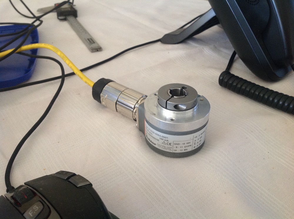
This is the encoder I will put on the spindle motor at the end of the shaft so I can keep the brake for safety reasons.
I was planning to post some pictures of the brake but the usb stick has fall on the elevators hole…lol
John
Last edit: 06 Oct 2017 12:07 by drimaropoylos.
Please Log in or Create an account to join the conversation.
- RotarySMP
-
Topic Author
- Offline
- Platinum Member
-
Less
More
- Posts: 1627
- Thank you received: 595
06 Oct 2017 12:10 #99995
by RotarySMP
Replied by RotarySMP on topic Retrofitting a 1986 Maho MH400E
Good shot with the USB stick down the elevator gap. Couldn't do it again if you tried
Whn you talk of "Spindle at speed" signal, was this signal generated from that encoder, or frm the VFD, or is it just an assumed value based on the worst case time for the spindle to accelerate. The MAHO set up can't generate that signal as built can it?
Mark
Whn you talk of "Spindle at speed" signal, was this signal generated from that encoder, or frm the VFD, or is it just an assumed value based on the worst case time for the spindle to accelerate. The MAHO set up can't generate that signal as built can it?
Mark
Please Log in or Create an account to join the conversation.
- drimaropoylos
- Offline
- Elite Member
-
Less
More
- Posts: 265
- Thank you received: 40
06 Oct 2017 12:36 #99998
by drimaropoylos
Replied by drimaropoylos on topic Retrofitting a 1986 Maho MH400E
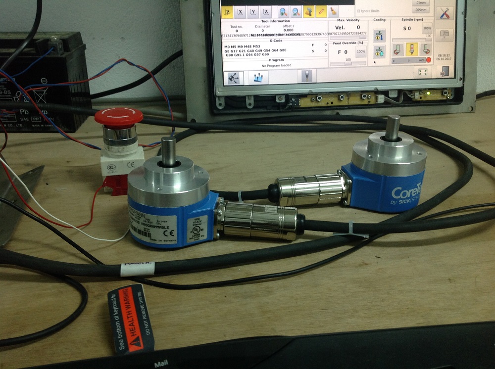
Those are the encoders for the servos.
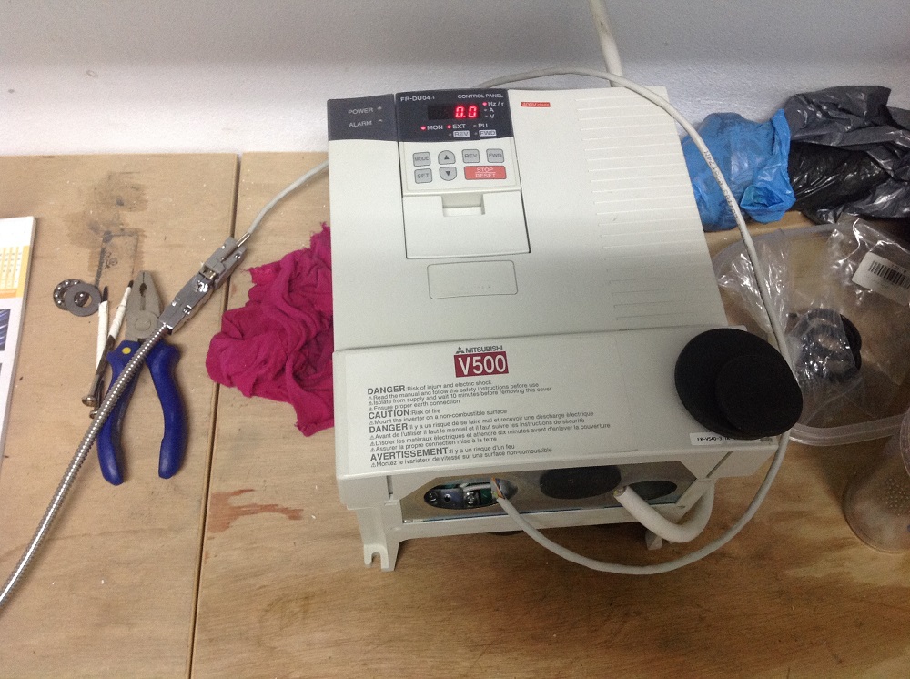
This is the vector drive for the spindle motor
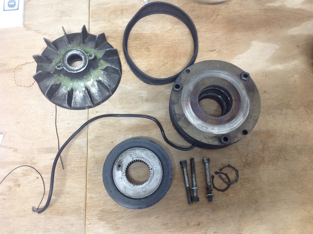
And the brake of the spindle motor
This is the vector drive for the spindle motor
And the brake of the spindle motor
Please Log in or Create an account to join the conversation.
Moderators: piasdom
Time to create page: 0.427 seconds