Retrofitting a 1986 Maho MH400E
- cgroth
- Offline
- Junior Member
-

Less
More
- Posts: 28
- Thank you received: 9
27 Oct 2017 19:24 #100894
by cgroth
Replied by cgroth on topic Retrofitting a 1986 Maho MH400E
Hi Mark,
I will start a new thread for the MH300C as soon as possible. Unfortunately I can't scan the manual before wednesday next week.
It is machine no. 35115, built in 1984. Software at delivery was 6104/311, but I didn't check it yet.
Yes, the CNC-controller is supplied from 150/151 but 7K1 and 7K2 connect the 3TRM2 and 1TRM2 (which can be installed for the 4. axis but is missing in my machine) to the transformer.
The spindle is driven by a TRK6-4U which mainly controls the motors field winding.
I have to check the gear box, unfortunately I left the manual at the machine yesterday so maybe tomorrow.
Christian
Please Log in or Create an account to join the conversation.
- RotarySMP
-
 Topic Author
- Offline
- Platinum Member
-

Less
More
- Posts: 1627
- Thank you received: 595
30 Oct 2017 17:16 - 09 Jan 2019 07:23 #101023
by RotarySMP
Replied by RotarySMP on topic Retrofitting a 1986 Maho MH400E
Unfortunately on friday, while installing radiators, I was raising one on end to install the pipe fittings when it slipped from my hands at 45° and fell like a guillotine. Broke three toes, and removed two toe nails. The Dr sewed the nails back on to protect the nail beds while the mess heals, but I have to keep the foot up for a week or so. I guess the MAHO is on hold for another week. I'll spare you the photos.
Dont forget your safety gear when working at home. My safety shoes were on the balcony because...
1/ they were dirty, and making tracks on the floor
2/ they are kind of uncomfortable, as they rubbed on the third toe (one of the ones that got broken and de-nailed).
In hindsight, lame reasons!!!
Mark
Dont forget your safety gear when working at home. My safety shoes were on the balcony because...
1/ they were dirty, and making tracks on the floor
2/ they are kind of uncomfortable, as they rubbed on the third toe (one of the ones that got broken and de-nailed).
In hindsight, lame reasons!!!
Mark
Last edit: 09 Jan 2019 07:23 by RotarySMP.
Please Log in or Create an account to join the conversation.
- jmelson
- Offline
- Moderator
-

Less
More
- Posts: 520
- Thank you received: 126
01 Nov 2017 02:30 #101095
by jmelson
(Seems like your sense of humor survived, too!)
Jon
Replied by jmelson on topic Retrofitting a 1986 Maho MH400E
THANK GOD! Having dropped heavy stuff on my toes more than a few times, it is NOT fun! Hope it all heals well!I'll spare you the photos.
(Seems like your sense of humor survived, too!)
Jon
The following user(s) said Thank You: RotarySMP
Please Log in or Create an account to join the conversation.
- drimaropoylos
- Offline
- Elite Member
-

Less
More
- Posts: 265
- Thank you received: 40
01 Nov 2017 19:23 #101146
by drimaropoylos
Replied by drimaropoylos on topic Retrofitting a 1986 Maho MH400E
HI, just saw the post, I’m very sorry for your accident. I wish you to have good recovery.
The following user(s) said Thank You: RotarySMP
Please Log in or Create an account to join the conversation.
- RotarySMP
-
Topic Author
- Offline
- Platinum Member
-
Less
More
- Posts: 1627
- Thank you received: 595
02 Nov 2017 08:19 #101178
by RotarySMP
Replied by RotarySMP on topic Retrofitting a 1986 Maho MH400E
Thanks guys. I did print out the missing brackets for the Heidenhain EXE mounting. Another think I can do with the foot up is start designing the pendant in CAD, and then print a prototype.
Please Log in or Create an account to join the conversation.
- RotarySMP
-
Topic Author
- Offline
- Platinum Member
-
Less
More
- Posts: 1627
- Thank you received: 595
04 Nov 2017 16:21 #101311
by RotarySMP
Replied by RotarySMP on topic Retrofitting a 1986 Maho MH400E
Sitting around is driving me nuts, but walking aggrevates the stitches pretty fast.
I pulled the controller board back out,
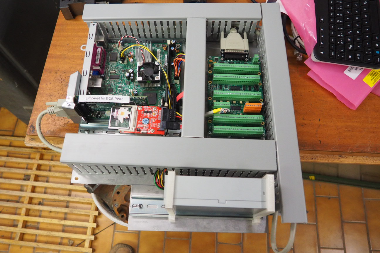
so I can set it up in my room and at least work on the HAL, Ini and Ladder files while I have my foot up.
Also got the EXE board mounted with its 3D printed blocks.
I was curious whether the output cable of the Heidenhain EXE carriers the differential signals, and the Phillips just didn't use them, or whether they were not output. I have no great hope of finding an old 1980's wiring diagram from the version of EXE MAHO used, so I am doing a dangerous assumption here. The product brochure of the more modern EXE gives the wiring colours, and I assume that a company like Heidenhain doesn't change them. The colors match up with the MAHO wiring diagrams.
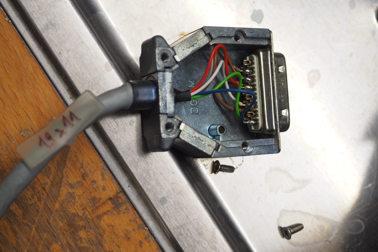
There were only five wires connected from the EXE to the phillips. A, B, Index, 0v and +5V. There are seven wires in the cable. What I find a bit weird is that the two unused signals would be two different systems.
- the unused Blue - test connection sensor voltage +
- the unused Green - B inverted.
I could see them either bring both test signals out, or both differential invertwed channels out. Maybe I am overthinking this. If I find I have noise issues, I can still try making new cables back to the EXE board, and bring out the differential inverted signals.

Mark
I pulled the controller board back out,
so I can set it up in my room and at least work on the HAL, Ini and Ladder files while I have my foot up.
Also got the EXE board mounted with its 3D printed blocks.
I was curious whether the output cable of the Heidenhain EXE carriers the differential signals, and the Phillips just didn't use them, or whether they were not output. I have no great hope of finding an old 1980's wiring diagram from the version of EXE MAHO used, so I am doing a dangerous assumption here. The product brochure of the more modern EXE gives the wiring colours, and I assume that a company like Heidenhain doesn't change them. The colors match up with the MAHO wiring diagrams.
There were only five wires connected from the EXE to the phillips. A, B, Index, 0v and +5V. There are seven wires in the cable. What I find a bit weird is that the two unused signals would be two different systems.
- the unused Blue - test connection sensor voltage +
- the unused Green - B inverted.
I could see them either bring both test signals out, or both differential invertwed channels out. Maybe I am overthinking this. If I find I have noise issues, I can still try making new cables back to the EXE board, and bring out the differential inverted signals.
Mark
Please Log in or Create an account to join the conversation.
- RotarySMP
-
Topic Author
- Offline
- Platinum Member
-
Less
More
- Posts: 1627
- Thank you received: 595
04 Nov 2017 16:46 #101312
by RotarySMP
Replied by RotarySMP on topic Retrofitting a 1986 Maho MH400E
I am just working through this thread...
forum.linuxcnc.org/27-driver-boards/3045...i25-7i77-first-steps
Thanks again to Andy Pugh for excellent clear support threads.
Mark
forum.linuxcnc.org/27-driver-boards/3045...i25-7i77-first-steps
Thanks again to Andy Pugh for excellent clear support threads.
Mark
Please Log in or Create an account to join the conversation.
- andypugh
-

- Offline
- Moderator
-
Less
More
- Posts: 19863
- Thank you received: 4636
04 Nov 2017 19:26 #101320
by andypugh
Replied by andypugh on topic Retrofitting a 1986 Maho MH400E
If there were differential signals, where is /Z ?
Please Log in or Create an account to join the conversation.
- RotarySMP
-
Topic Author
- Offline
- Platinum Member
-
Less
More
- Posts: 1627
- Thank you received: 595
05 Nov 2017 11:08 #101345
by RotarySMP
Replied by RotarySMP on topic Retrofitting a 1986 Maho MH400E
Hello Andy,
Currently, the only differential signal which appears to have been brought out on the cable is Ua1 which you would normally call /A. The other two differential signals Ua0 = /Z and Ua2 = /B should be available on the EXE board at the pin head connector in pins 4 and 1 respectively according to the Heindenhain product info I linked in my last post. If I have noise issues, I'll have to make up a new cble to that green pinhead connector.
For those who speak german, youtuber Talla83 has some really good videos on the MESA cards which I found very helpful...
www.youtube.com/channel/UCHDMxw4Oum-wKm5UpMt2lzA
Mark
Please Log in or Create an account to join the conversation.
- RotarySMP
-
Topic Author
- Offline
- Platinum Member
-
Less
More
- Posts: 1627
- Thank you received: 595
05 Nov 2017 12:12 - 05 Nov 2017 16:27 #101348
by RotarySMP
Replied by RotarySMP on topic Retrofitting a 1986 Maho MH400E
I have the 5i25, 7i77 and 7i84 all installed and powered, and seem to have the whole complement of pins when I run " show pins".
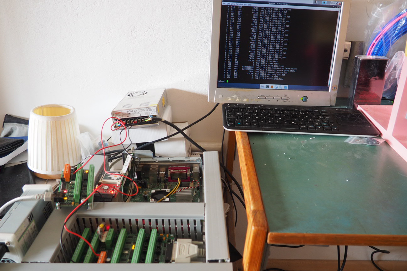
Just a question about putting the 7i77 in mode 3 to read the jog wheel encoder. Do I need to put the following command into my machine.HAL file, or is this a sticky setting which I only need to send to the 7i77 once, and it remains in that mode despite restarts?
loadrt hm2_pci config="sserial_port_0=300xxx"
[Edit] PNCConf answered my question. It out in set up line in the HAL which includes the config="sserial_port_0=000xxx so I just changes it to 300xxx.
Mark
Last edit: 05 Nov 2017 16:27 by RotarySMP.
Please Log in or Create an account to join the conversation.
Moderators: piasdom
Time to create page: 0.860 seconds