Kitamura Mycenter 0 ATC ARM Help
- DaOne
-
 Topic Author
- Offline
- Premium Member
-

Less
More
- Posts: 155
- Thank you received: 6
29 Jan 2020 09:47 #156076
by DaOne
Kitamura Mycenter 0 ATC ARM Help was created by DaOne
I am trying to reverse engineer the tool changer arm on this Kitamura Mycenter 0 I have been retrofitting with Linuxcnc. The factory proximity sensors (trip locations) are not making much sense to me. The ATC Arm is powered via a VFD. All the motions are performed by a CAM. It does however have original inputs for CW, CCW, Speed 1, Speed 2 and Reset. The slow speed is for maintenance only. I am trying to figure out how the events are triggered for tool clamp / unclamp. It does not look straight forward to me (Could be lack of sleep). I am hoping someone can help me decipher the original ladder logic? I would like to write a component to handle this but I am having trouble understanding the sequencing. The ability for the arm to go both CW and CCW is really stumping me as well. I shot some slow motion video of the arm in low speed with the sensor activity displayed on the screen. This is just running continuous in CW or CCW directions. From every video I have seen on Youtube it appears it should be moving in the CCW direction. Any help on this is appreciated. I am including docs and videos below.
ATC Arm Proximity Sensors and ladder input address (Just the arm sensors)...
10081 ATC CAM Zero
10044 ATC Cammotor Stop Pos
10045 ATC Unlamp Pos (Not used or even installed in this machine)
10040 Tool Clamp Fin
Video of the arm VFD running CW...
Video of the arm VFD running CCW...
Video of tool change (Not my machine but the same model)
Ladder Diagrams...
www.dropbox.com/s/qjgb8urkird9jkd/Kit%20...0Searchable.pdf?dl=0
Electrical Diagrams...
www.dropbox.com/s/k68bkkealpbji1d/kit%20electrical.pdf?dl=0
The following user(s) said Thank You: tommylight
Please Log in or Create an account to join the conversation.
- DaOne
-
Topic Author
- Offline
- Premium Member
-
Less
More
- Posts: 155
- Thank you received: 6
29 Jan 2020 09:59 #156077
by DaOne
Replied by DaOne on topic Kitamura Mycenter 0 ATC ARM Help
Also I forgot... I am running a minimalistic pyvcp config just to display these LED indicators. The servo thread running these indicators is 1000000 nanoseconds. I am shooting this video at 240fps. I am wondering if I am just seeing latency of the display LEDS and thats whats stumping me?
Please Log in or Create an account to join the conversation.
- andypugh
-

- Offline
- Moderator
-

Less
More
- Posts: 19875
- Thank you received: 4642
06 Feb 2020 15:35 #156640
by andypugh
Replied by andypugh on topic Kitamura Mycenter 0 ATC ARM Help
Did you get anywhere with this?
Please Log in or Create an account to join the conversation.
- DaOne
-
Topic Author
- Offline
- Premium Member
-
Less
More
- Posts: 155
- Thank you received: 6
06 Feb 2020 16:03 #156641
by DaOne
Replied by DaOne on topic Kitamura Mycenter 0 ATC ARM Help
No I have not. I moved on to replace thrust bearings and redo the entire lube system. I am ready however at anytime if you have any suggestions. My next step was to rig up some LEDs directly to the proximity sensors to test the latency.
Please Log in or Create an account to join the conversation.
- andypugh
-
- Offline
- Moderator
-
Less
More
- Posts: 19875
- Thank you received: 4642
06 Feb 2020 16:37 #156642
by andypugh
Replied by andypugh on topic Kitamura Mycenter 0 ATC ARM Help
All the proximity sensors I have have LEDs built in. Have you looked?
Please Log in or Create an account to join the conversation.
- DaOne
-
Topic Author
- Offline
- Premium Member
-
Less
More
- Posts: 155
- Thank you received: 6
06 Feb 2020 17:00 #156643
by DaOne
Replied by DaOne on topic Kitamura Mycenter 0 ATC ARM Help
Yes these do as well but the sensors are not easy to see. Kinda hidden under the sheet metal. No way I could catch those in a video with the arm motion and the screen to test timing.
Please Log in or Create an account to join the conversation.
- drimaropoylos
- Offline
- Elite Member
-

Less
More
- Posts: 265
- Thank you received: 40
08 Feb 2020 19:17 #156772
by drimaropoylos
Replied by drimaropoylos on topic Kitamura Mycenter 0 ATC ARM Help
A few thing that may help you. They are different types of “relays” in the ladder schematics
1. ladder internal relays to build the logic
2. output relays for control components of the machine
3. output relays witch they are inputs to the cnc controller
4. the square stuff witch they are timers
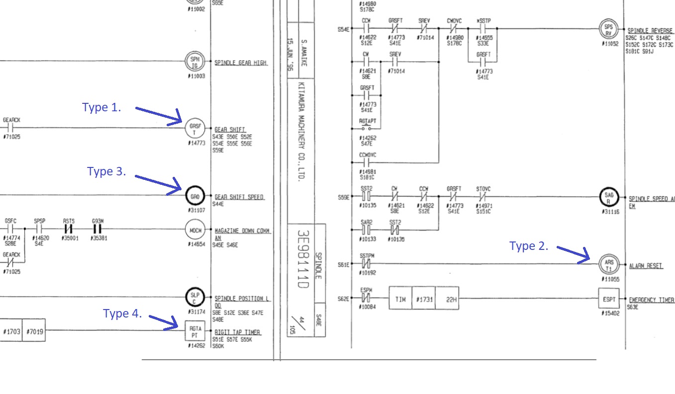
1. ladder internal relays to build the logic
2. output relays for control components of the machine
3. output relays witch they are inputs to the cnc controller
4. the square stuff witch they are timers
Attachments:
Please Log in or Create an account to join the conversation.
- drimaropoylos
- Offline
- Elite Member
-
Less
More
- Posts: 265
- Thank you received: 40
08 Feb 2020 19:28 #156774
by drimaropoylos
Replied by drimaropoylos on topic Kitamura Mycenter 0 ATC ARM Help
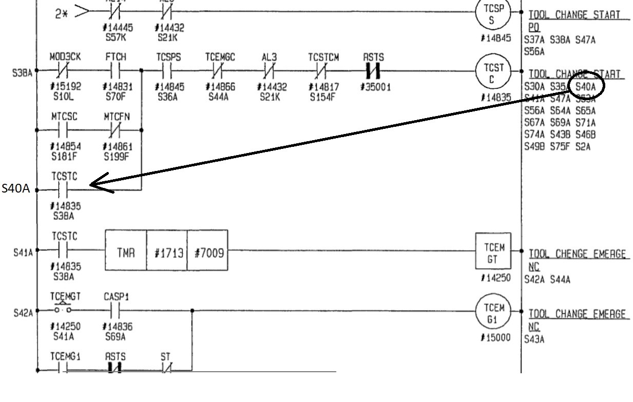
Every relay has a number and the numbers below the description of the relay is the place of the contacts of that relay.
Attachments:
The following user(s) said Thank You: DaOne
Please Log in or Create an account to join the conversation.
- drimaropoylos
- Offline
- Elite Member
-
Less
More
- Posts: 265
- Thank you received: 40
08 Feb 2020 19:50 #156778
by drimaropoylos
Replied by drimaropoylos on topic Kitamura Mycenter 0 ATC ARM Help
10044 tells the plc to slow down the arm because is close to the tool holder
10040 tells the plc that the tool holder is clamped and it is ok to proceed to relise the tool and continue with the rest of the arm movement
10081 tells the plc that the arm is in home position and the program may continue
John
10040 tells the plc that the tool holder is clamped and it is ok to proceed to relise the tool and continue with the rest of the arm movement
10081 tells the plc that the arm is in home position and the program may continue
John
The following user(s) said Thank You: DaOne, tommylight
Please Log in or Create an account to join the conversation.
- DaOne
-
Topic Author
- Offline
- Premium Member
-
Less
More
- Posts: 155
- Thank you received: 6
08 Feb 2020 21:01 #156782
by DaOne
Replied by DaOne on topic Kitamura Mycenter 0 ATC ARM Help
John, thank you! For the most part I figured out the way to read the ladder logic. (Just hard for my mind to follow it) I do need to figure out the timer blocks however. I am thinking I might just start putting this whole thing into classic ladder and watch how its working. I am worried that timing is super critical. The actual tool change on this machine is super fast. Under .8 of a second.
Things I am still trying to figure out...
*Does it only go in one direction or does it change direction in some point of the cycle? Trying to understand why there is a CW and a CCW?
*Does it use the timers in the later logic as delays for the proximity sensors?
*The timer blocks.. What does the first and 2nd value actually mean? I have the values but no idea what the represent. On delay off delay?
*In classic ladder fast enough to handle timings like this if thats whats required?
Please Log in or Create an account to join the conversation.
Moderators: piasdom
Time to create page: 0.740 seconds