
- Posts: 63
- Thank you received: 6
Retrofitting a TOS FNG 32 NC
- Kevin_Pawlus
- Topic Author
- Offline
- Senior Member
-

Less
More
4 years 3 months ago #247164
by Kevin_Pawlus
Replied by Kevin_Pawlus on topic Retrofitting a TOS FNG 32 NC
Alrigt, I have ordered 1 pice 7i77 and 7i94 and it should be here on thursday.
I have photographed the drawings and will upload them on drive when I get Wifi again.
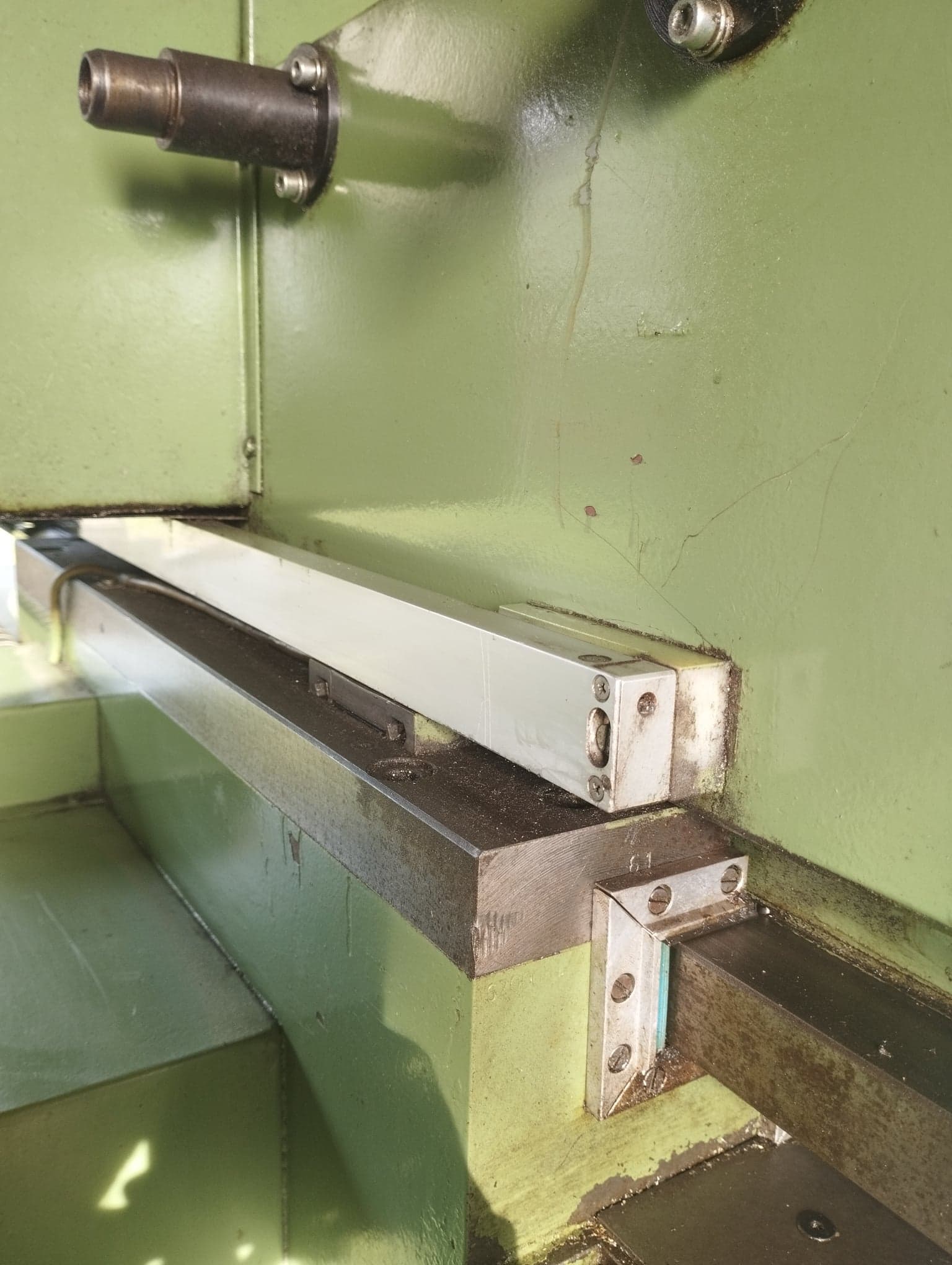
I've started to see if I can find everything on the machine. So far I have identified all of the 0-10v motor control cables and linear sensors.
Have I understand it correct that there is one enable signal to the motor and +10v means full speed one direction and -10v full speed the other direction?
I have not seen any model number or anything on my linear sensors, I'm not sure how they work and how to plug them in the Mesa board.
I have photographed the drawings and will upload them on drive when I get Wifi again.
I've started to see if I can find everything on the machine. So far I have identified all of the 0-10v motor control cables and linear sensors.
Have I understand it correct that there is one enable signal to the motor and +10v means full speed one direction and -10v full speed the other direction?
I have not seen any model number or anything on my linear sensors, I'm not sure how they work and how to plug them in the Mesa board.
Please Log in or Create an account to join the conversation.
- tommylight
-
- Offline
- Moderator
-

4 years 3 months ago #247166
by tommylight
Yes.
The enable is usually a pin that has to be tied to ground/common to enable the drives, not always.
That and more should be in the schematics, avoids making assumptions.
Replied by tommylight on topic Retrofitting a TOS FNG 32 NC
Have I understand it correct that there is one enable signal to the motor and +10v means full speed one direction and -10v full speed the other direction?
Yes.
The enable is usually a pin that has to be tied to ground/common to enable the drives, not always.
That and more should be in the schematics, avoids making assumptions.
Please Log in or Create an account to join the conversation.

4 years 3 months ago #247169
by Henk
Replied by Henk on topic Retrofitting a TOS FNG 32 NC
The siemens 6rb drives generally have more than one enable.
IIRC....pulse enable, regulator anable and axis enable.
i have had problems when trying yo enable all of them at the same time.
On my last retrofit, i enable the pulse and regulator together, when estop is released, and axis when the machine is switched on.
IIRC....pulse enable, regulator anable and axis enable.
i have had problems when trying yo enable all of them at the same time.
On my last retrofit, i enable the pulse and regulator together, when estop is released, and axis when the machine is switched on.
Please Log in or Create an account to join the conversation.
- Kevin_Pawlus
- Topic Author
- Offline
- Senior Member
-
Less
More
- Posts: 63
- Thank you received: 6
4 years 3 months ago #247171
by Kevin_Pawlus
Replied by Kevin_Pawlus on topic Retrofitting a TOS FNG 32 NC
I have identified one enable, nr85. Now I try to read what voltage it needs in the Siemens manual, it comes right from the Heidenhain module.
nr56 & nr14 is +-10V.
It says "GO" on the left side. Can that also be one enable?
Is G1, G2, G3 encoders and should in the future be connected to Mesa?
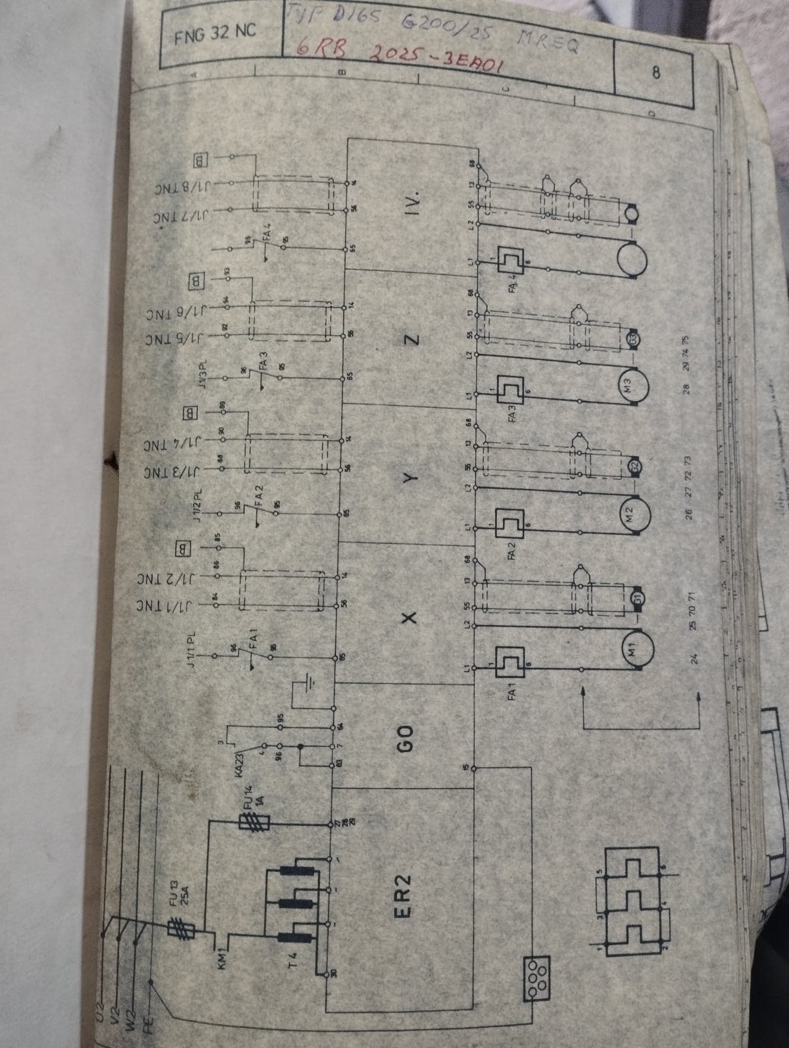
nr56 & nr14 is +-10V.
It says "GO" on the left side. Can that also be one enable?
Is G1, G2, G3 encoders and should in the future be connected to Mesa?
Please Log in or Create an account to join the conversation.
4 years 3 months ago #247173
by Henk
Replied by Henk on topic Retrofitting a TOS FNG 32 NC
ER2 is the power supply sectiom of thw drive. It consists of a rectifier and a cap that rectifies the 165vac 3 phase from the transformer shown. Terminal 27 28 and 29 get 3 phase line voltage and powers the electronics.
G0 is another card in the drive. It contains the pulse and regulator enable signals. Pin 7 here is 24v dc to be used to enable the drive as shown on pins 63 (permanently enabled) and 64 through the relay contacts.
each axis, in your case 4 of them has its own speed control card. For each of them, pin 65 is the enable for that axis. This enable power should also come from pin 7 on the G0 card.
G1 ....G3 are dc tachogenerators mounted on the motors. They provide velocity feedback to the drive. Take note of the polariry of the motor supply wires and the tacho wires and dont mix them up or swap the polarity. It will cause the motor to run away and can damage the power transistors. These tacho signals stay as is and will not be connected to anything else.
the linear scale signals must go to the mesa 7i77. You need to check what type of signal is coming from the scales. You may need interpolators to convert from sin/cos to 5v ttl. Check the diagrams for something labled EXE...
Please Log in or Create an account to join the conversation.
- Kevin_Pawlus
- Topic Author
- Offline
- Senior Member
-
Less
More
- Posts: 63
- Thank you received: 6
4 years 3 months ago #247175
by Kevin_Pawlus
Replied by Kevin_Pawlus on topic Retrofitting a TOS FNG 32 NC
Thanks for the reply
I meant nr 65, not nr85 before. Okay, so I take the voltage from pin 7 and connect it through a relay and then on to nr65 and when the relay is on the motor is enabeld?
After I have enable the whole drive with KA23.
The linear scales are Hedenhain LS403.
There is some electrical info on page 20 here but Im still unsure what signal.
siebert-automation.com/wp-content/upload...ing-Instructions.pdf
Please Log in or Create an account to join the conversation.
Time to create page: 0.362 seconds