Designing DIY CNC Milling Machine

More
3 years 1 month ago #280637 by spumco

I've got two questions:
- Do you have any suggestions about any other products like Rapid-Set? In Poland I was able to find only one place where they sell it, but no way to purchase the Flow Control additive.
- With basalt fibers, is this possible to later drill in that? I'm curious if I definitely need to put inserts everywhere I might need these, or will this be possible to attach something later (I'm thinking stuff like chip guards, bellows, etc). What kind of inserts will work best?


I am not aware of any other CSA cement-based products in the US, and I've no idea about EU sourcing.

However... the Flow Control should be a 'normal' superplasticizer, but I think it's got some citric acid mixed in.  My limited research indicates citric acid is the appropriate retarder for CSA cement, and it makes sense they'd add a bit of retarder to a plasticizer.

I think it'd be worth a $20 experiment to see if another brand of superplasticizer works with Rapid Set without causing problems.  The Rapid-Set site has details on Flow Control dosing.  You could also contact CTS and see if they know of a distributor in your area for Flow Control and retarder additives.

SDS for Rapidset's Flow Control attached.  Not very helpful, but I did see citric acid in there.


The basalt fibers I used are loose, not in rebar form; they are mixed in to the mortar before casting/placing in the mold.

As far as inserts go, you really don't want to drill and glue stuff in later.  Concrete slabs & objects are drilled all the time for connecting pins and anchors, but the resulting joint is extremely sensitive to surface prep and they really don't have much tensile strength even when done properly.

If you need attachment points (threaded holes) for accessories, my suggestion would be to cast through-tubes in the component and then bolt & bond steel plates to the outside surface.  The through-tubes would be used to pass threaded rod all the way through the casting, and two opposing plates are then clamped down (picture a sandwich).  Epoxy could be used as a bedding grout between the plate and the cast surface if you want a really stable & rigid mounting surface.

The tubes can be formed simply by using some plastic water pipe with an ID slightly larger than the threaded rod to be used later.  If you take a close look at the photo I posted you can see some plastic tubes protruding from the casting.  Those are for access holes to otherwise-obscured fasteners on the Y-axis saddle, as well as through-holes to bolt the column to the base.

Similar construction could be used for steel bars to be later used as linear rail or ballscrew support mounting surfaces.


Please Log in or Create an account to join the conversation.

More
3 years 1 month ago - 3 years 1 month ago #280639 by slawekgonet
This actually leads me to another question. How to properly attach steel frame to the concrete?

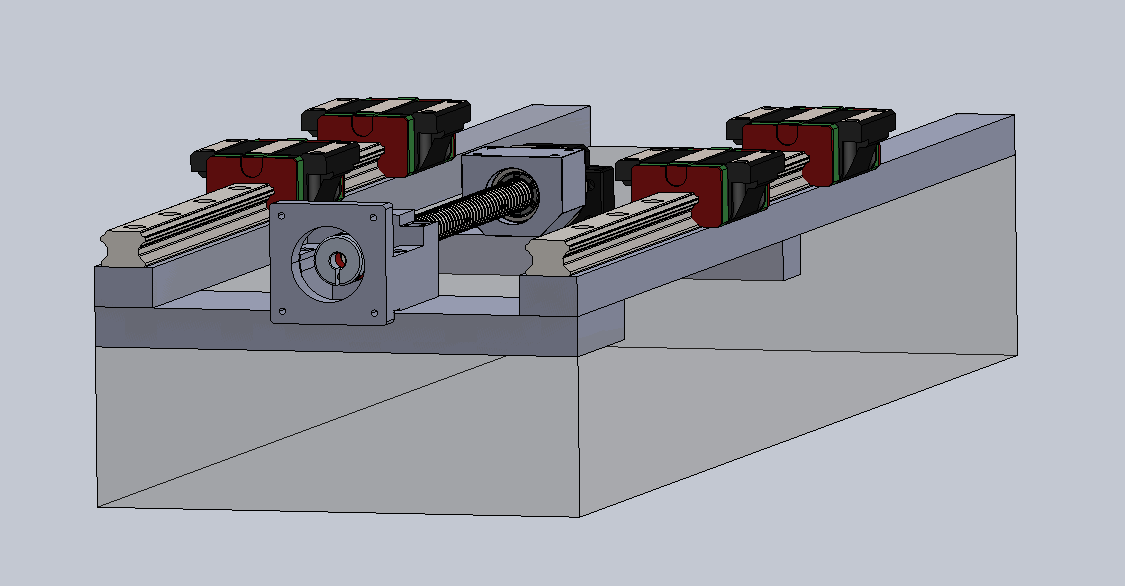
Let's say something like that: 
How would you anchor that metal frame in casting? Or should I mount everything with through-tubes and long threaded rods?

EDIT:

That made me wonder. Do I even need the internal steel frame if I'm going to use some shimming epoxy anyways? I could make the cement casting so there will be slightly oversized holes pre-cast with counterbores to accept nuts from the bottom - so the rails will bolt straight to the casting, compressing it?

 
Last edit: 3 years 1 month ago by slawekgonet.

Please Log in or Create an account to join the conversation.

More
3 years 1 month ago #280696 by spumco
I would go with the through-tubes and bearing plates on the outside.

I'll try to draw something up for you to think about, but it'll be mostly like your sketch.

Please Log in or Create an account to join the conversation.

More
3 years 1 month ago #280700 by spumco
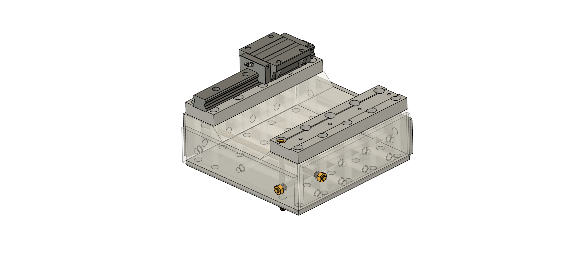
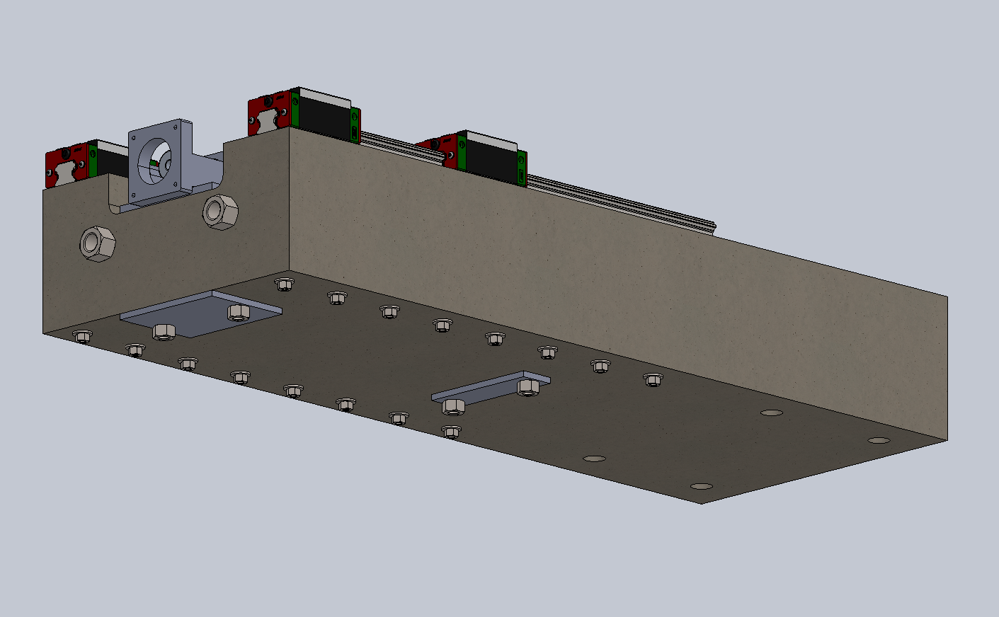
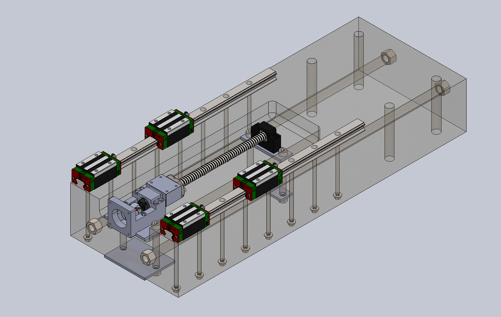
Here's something I whipped up.

All surfaces have steel bearing plates with 10mm threaded rods putting everything in compression.  For scale, I modeled the top rail plates at 75mm wide x 25mm thick.  Linear rail is a THK SHS35 series.

A better design would have the plates all welded together - especially at the corners - to improve torsional stiffness.  But at that point you might as well weld up a steel form and cast the whole thing in place, then install and tighten the threaded rods after the Rapidset has cured for a few days.

Top rail plates would be left off the casting and pre-machined.  Once the thing has set up, the rails are bedded in epoxy and the whole thing flipped upside down on a surface plate so they cure co-planar.  Once cured, the rods are fully tensioned.

Obviously, this isn't a real, final design but I've tried to incorporate some design elements for you to consider.


Please Log in or Create an account to join the conversation.

More
3 years 1 month ago - 3 years 1 month ago #280708 by slawekgonet
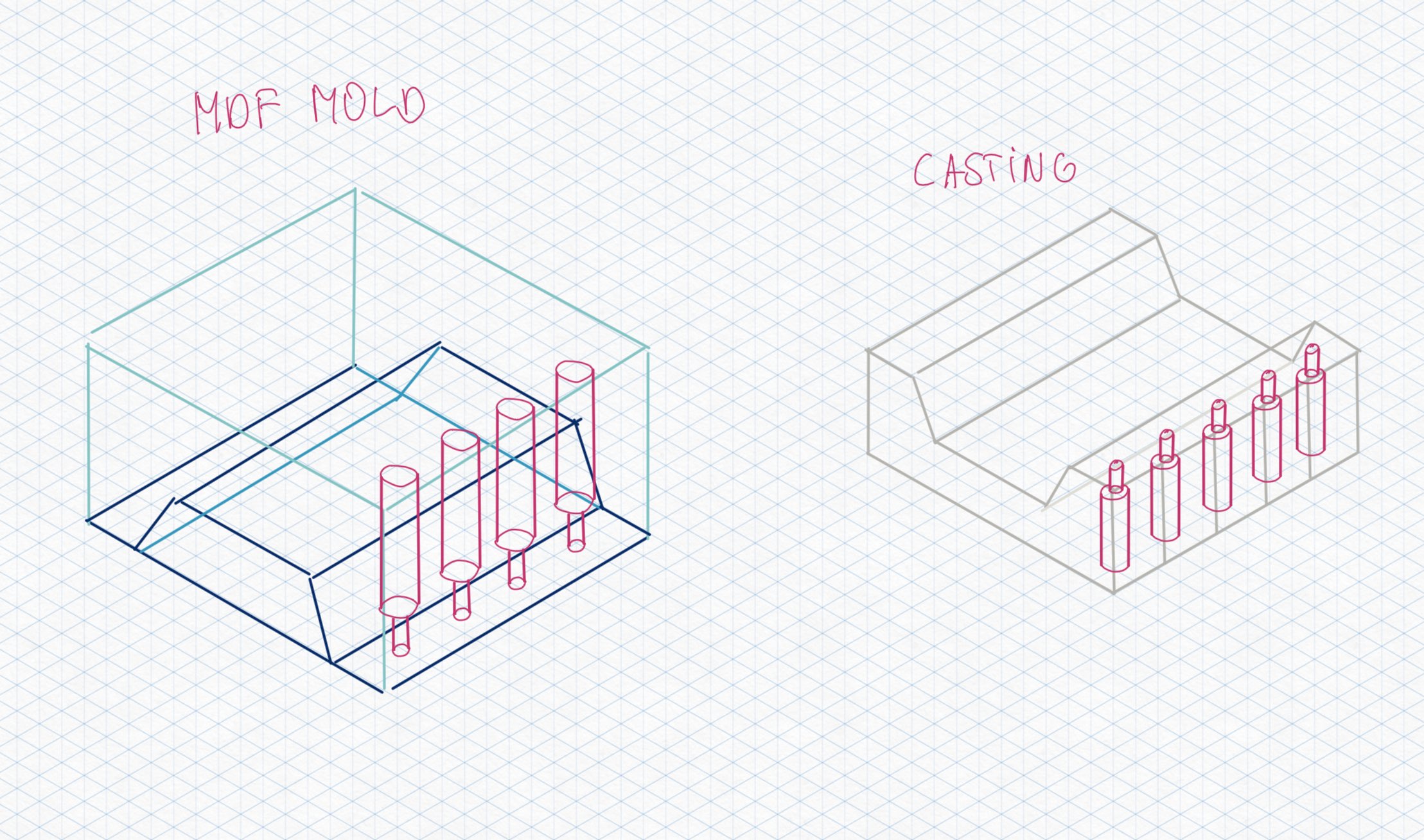
Thanks. Something like that will be definitely superior compared to what I had in mind (that's Y axis):

- Rails are bolted with long M6 screws via through-holes with some reasonably big washers on the bottom.
- Two M16 threaded rods with washers to compress the casting in Y direction.


Some reasons behind that:
- Steel, especially larger pieces like needed here, is very expensive. I don't have any local shop around, only way is to order online and that is expensive.
- I don't have access to milling machine large enough to make any kind of supporting structure under rails that will be precise enough. Since linear rails themselves are already big flats capable of taking some tensioning pressure with through-bolts.
- About the casting form - I was planning to make it out of MDF, spray it with some release agent. I also though about screwing the rails on the outside of the mold to locate the through holes for them and also maybe help a bit with dimensional accuracy by screwing MDF to straight rails. I still assume that shimming epoxy will be necessary.

I am aware that ideally I should put the RapidSet under pressure from every direction with bearing plates, but I'm at least considering what options I have. Do you think something like that is reasonable compromise or CSA without bearing plates all around makes no sense?
Last edit: 3 years 1 month ago by slawekgonet.

Please Log in or Create an account to join the conversation.

More
3 years 1 month ago #280732 by spumco
I think it's a reasonable compromise.  If steel is prohibitively expensive, work with what you've got.

If you can't get steel plates, large diameter, thick washers can be substituted.

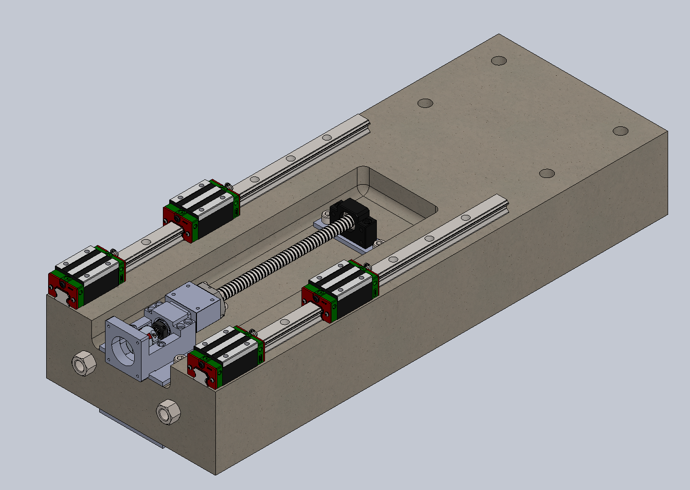
Also - consider eliminating the 'trough' for the ballscrew.  If you upsize your rails & trucks and cast a relief pocket in the bottom of the saddle, you now have a flat surface for the rails and ballscrew.  It'd be much easier to get everything co-planer, and you don't have two unreinforced protrusions subject to side-loading (and cracking).  You also don't have something that will turn in to a chip/swarf trap.

Please Log in or Create an account to join the conversation.

Time to create page: 0.271 seconds
Powered by Kunena Forum