Emergency Stop Circuit
- Type_Zero_Design
- Offline
- Premium Member
-

Less
More
- Posts: 133
- Thank you received: 7
22 Jul 2019 04:46 #140147
by Type_Zero_Design
Emergency Stop Circuit was created by Type_Zero_Design
I am planning to implement a hardware emergency stop circuit using a contactor on the mains that will be latched via the coil voltage accross an additional terminal on the contactor after the NO ready switch energizes the coil. Similar to a motor Start/Stop Circuit.
This circuit relies on the NC ESTOP switches to be wired in series of the latched coil voltage, so when depressed it opens the coil circuit and disconnects the mains.
My question is how do I tie in my control to this to have the the ability to TRIGGER an Estop via software? I will have an additional terminal that will tell the control when the contactor is in estop state.
Any ideas are appreciated.
Please Log in or Create an account to join the conversation.
- rodw
-

- Offline
- Platinum Member
-

Less
More
- Posts: 11945
- Thank you received: 4066
22 Jul 2019 05:29 #140148
by rodw
Replied by rodw on topic Emergency Stop Circuit
Its not really well documented but you can create an estop chain in software using estop-latch. I have several things that can trigger an estop including the software button activated in this way. I think the docs just show a software and hardware estop button chained together. but the chain can be extended.
Please Log in or Create an account to join the conversation.
- pl7i92
-

- Offline
- Platinum Member
-
Less
More
- Posts: 1872
- Thank you received: 358
22 Jul 2019 07:54 #140158
by pl7i92
Replied by pl7i92 on topic Emergency Stop Circuit
a simple or chaining can also do the trick and it very easy to read in hal
also to setup and view the nets in GUI as pyvcp led perhaps
also to setup and view the nets in GUI as pyvcp led perhaps
Please Log in or Create an account to join the conversation.
- Type_Zero_Design
- Offline
- Premium Member
-
Less
More
- Posts: 133
- Thank you received: 7
23 Jul 2019 03:37 #140260
by Type_Zero_Design
Replied by Type_Zero_Design on topic Emergency Stop Circuit
What I'm trying to figgure out is on the hardware side. Once that estop signal is is generated in software, how can I use that signal to physically break the circuit powering the coil that is keeping the contactor latched supplying mains power? I need it to work in a way similar to depressing a NC ESTOP switch in that circuit and forcing the circuit open dropping power from the coil and unlatching it until the alarm is cleared and the ready button is pressed again.
Please Log in or Create an account to join the conversation.
- Type_Zero_Design
- Offline
- Premium Member
-
Less
More
- Posts: 133
- Thank you received: 7
23 Jul 2019 03:56 #140261
by Type_Zero_Design
Replied by Type_Zero_Design on topic Emergency Stop Circuit
Also would it be an issue to switch a 24v "coil" on an SSR using the 24v output on my 77i76e? I'm not sure what the draw is on the 24v "coil" side of the relay is.
Please Log in or Create an account to join the conversation.
- tommylight
-

- Offline
- Moderator
-

Less
More
- Posts: 21617
- Thank you received: 7383
23 Jul 2019 08:32 #140275
by tommylight
Replied by tommylight on topic Emergency Stop Circuit
SSR use litle current to activate, so using 7i76 field outputs is safe, just check the alowed voltage for the SSR, almost all that i have are strictly 5V. That can be aranged with a single resistor, but some testing is in order if it does not have the current writen ( usually they do not ), or use a lab power supply to check how much it draws at 5V and calculate the resistor value based on that.Also would it be an issue to switch a 24v "coil" on an SSR using the 24v output on my 77i76e? I'm not sure what the draw is on the 24v "coil" side of the relay is.
Please Log in or Create an account to join the conversation.
- Type_Zero_Design
- Offline
- Premium Member
-
Less
More
- Posts: 133
- Thank you received: 7
24 Jul 2019 04:47 #140394
by Type_Zero_Design
Replied by Type_Zero_Design on topic Emergency Stop Circuit
This is what I have in mind for my estop circuit. Would like to hear thoughts.
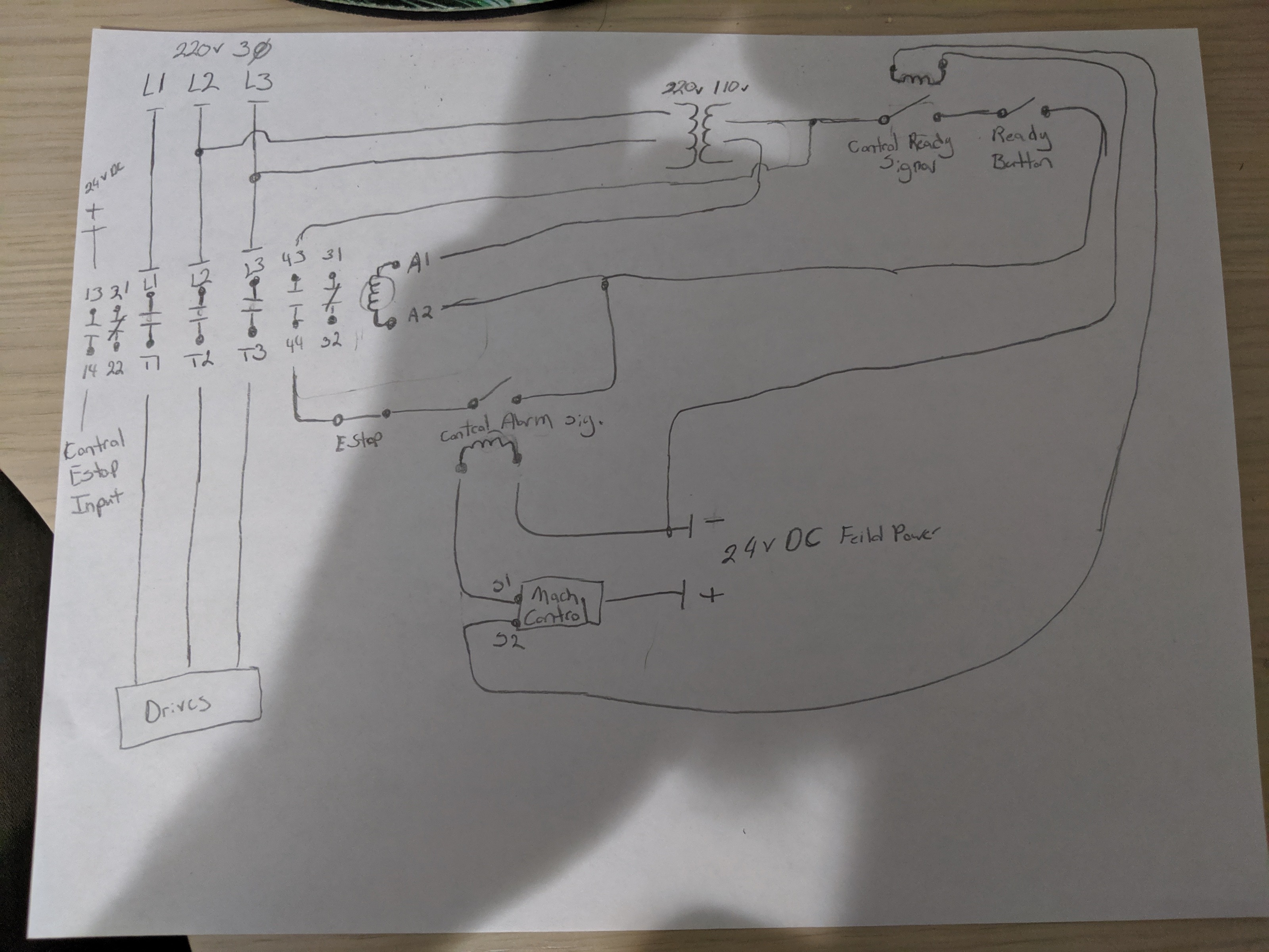
Attachments:
Please Log in or Create an account to join the conversation.
- Type_Zero_Design
- Offline
- Premium Member
-
Less
More
- Posts: 133
- Thank you received: 7
24 Jul 2019 04:53 - 24 Jul 2019 04:53 #140395
by Type_Zero_Design
Replied by Type_Zero_Design on topic Emergency Stop Circuit
After looking at this I think I can simplify the circuit like this and remove the dedicated kill relay and just rely on the machine ready signal to be closed and open when estop is active. This would allow the control to mechanicly trip the circuit while also ensuring that the control is completely booted prior to allowing you topress the ready button and and power mains.
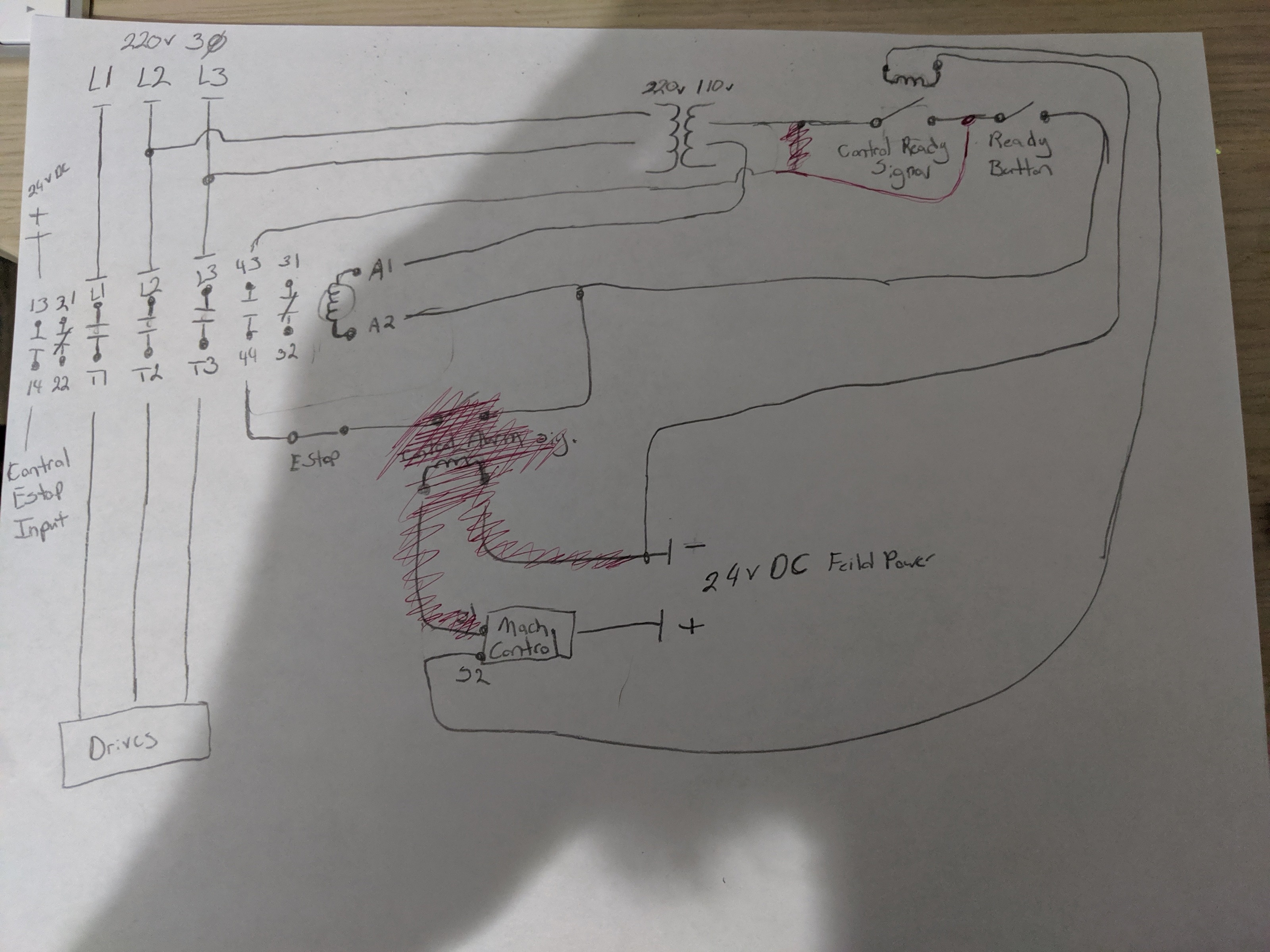
Attachments:
Last edit: 24 Jul 2019 04:53 by Type_Zero_Design.
Please Log in or Create an account to join the conversation.
- Hakan
- Offline
- Platinum Member
-
Less
More
- Posts: 1317
- Thank you received: 453
24 Jul 2019 08:05 - 24 Jul 2019 08:14 #140410
by Hakan
Replied by Hakan on topic Emergency Stop Circuit
I can just share with you some ideas. I am currently designing the electric part of my milling machine.
I am not a proffesional but I usually figure things out in the end.
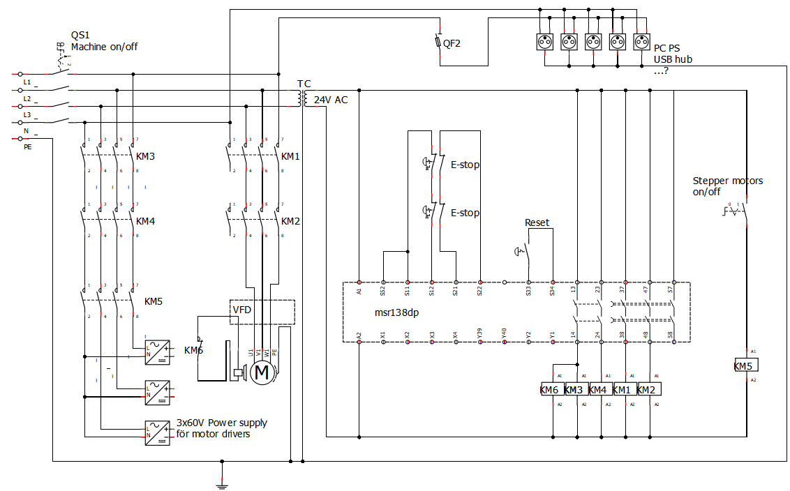
I have based the E-stop circuit around a safety relay. It is all hardware. Linuxcnc is not invited to take part.
In an emergency stop, I need the spindle to stop and the axis's motors to stop.
I can just shut off the power to those, but the spindle will have 2-3 seconds to brake the rotation before shutting power off.
I don't think of linuxcnc's e-stop as a real e-stop. If linuxcnc is operational it can do a controlled stop (c-stop?") ), it really doesn't need to shut off the power. I may take the real e-stop signal into linuxcnc so it knows that an e-stop has occured, but that's all.
), it really doesn't need to shut off the power. I may take the real e-stop signal into linuxcnc so it knows that an e-stop has occured, but that's all.
I am not a proffesional but I usually figure things out in the end.
I have based the E-stop circuit around a safety relay. It is all hardware. Linuxcnc is not invited to take part.
In an emergency stop, I need the spindle to stop and the axis's motors to stop.
I can just shut off the power to those, but the spindle will have 2-3 seconds to brake the rotation before shutting power off.
I don't think of linuxcnc's e-stop as a real e-stop. If linuxcnc is operational it can do a controlled stop (c-stop?
), it really doesn't need to shut off the power. I may take the real e-stop signal into linuxcnc so it knows that an e-stop has occured, but that's all. Attachments:
Last edit: 24 Jul 2019 08:14 by Hakan.
Please Log in or Create an account to join the conversation.
- Type_Zero_Design
- Offline
- Premium Member
-
Less
More
- Posts: 133
- Thank you received: 7
24 Jul 2019 12:19 #140425
by Type_Zero_Design
Replied by Type_Zero_Design on topic Emergency Stop Circuit
Hakan,
I'm going to do some research on the safety relays, but I am kind of confused by your post. It sounds like you are saying that you don't just want to cut the mains power via a contactor or something similar when an E-stop is triggered because you are concerned about coasting. Which I think is valid. But at the same time you said that you are not using or trusting LCNC to function as ESTOP which I agree with as well. So what are you planing to do then to prevent the 2-3 second of rotation but not use LCNC to command an off command?
Also looking at your diagram. (which is very nice by the way curious what you used to make it) It looks like you are using contactors/relays to disconnect power to your drives and VFD controlled by the safety relay. I'm assuming the two on each are just for redundancy?
Please Log in or Create an account to join the conversation.
Moderators: PCW, jmelson
Time to create page: 0.264 seconds