Emergency Stop Circuit
- Richard J Kinch
-

- Offline
- Senior Member
-

Less
More
- Posts: 61
- Thank you received: 4
26 Jul 2019 05:44 - 26 Jul 2019 05:48 #140615
by Richard J Kinch
This is accomplished with the same logic as any ON/OFF control with multiple AND input factors.
Be sure not to create a deficient logic design and severe hazard by overlooking another stop state complication:
Your contactor should not energize if the mains power fails and then comes back on. You need a manual, dedicated, momentary, physical START button that must be manually actuated to energize the contactor under all possible states and event paths, not just an ON/OFF breaker or E-STOP. An E-STOP alone is not enough. It must be manual-only with no automatic operation possible.
So you must have an extra button, and an extra relay, in the system, that prevents the system from self-starting if the switches are left on with the mains power off. Otherwise you have the hazard of machinery starting unexpectedly if your attention lapses around a power interruption. The mains supply from the utility amounts to another logic state in the system, so don't forget to include that in your logic state diagram and planning.
The simplest method is to have the contactor signal supply voltage downstream of the contactor, with a momentary START button that manually backfeeds the contactor coil, to "bootstrap" the contactor to its on state. You want that bootstrap action to always be the manual effort of an intelligent human being, never automatic, and never a state switch.
This way, if the mains power drops out on the running machine, the machine doesn't start running again when the power returns. A power dropout is something that always needs manual attention.
Replied by Richard J Kinch on topic Emergency Stop Circuit
I am planning to implement a hardware emergency stop circuit using a contactor on the mains ... how do I tie in my control to this to have the the ability to TRIGGER an Estop via software?
This is accomplished with the same logic as any ON/OFF control with multiple AND input factors.
Be sure not to create a deficient logic design and severe hazard by overlooking another stop state complication:
Your contactor should not energize if the mains power fails and then comes back on. You need a manual, dedicated, momentary, physical START button that must be manually actuated to energize the contactor under all possible states and event paths, not just an ON/OFF breaker or E-STOP. An E-STOP alone is not enough. It must be manual-only with no automatic operation possible.
So you must have an extra button, and an extra relay, in the system, that prevents the system from self-starting if the switches are left on with the mains power off. Otherwise you have the hazard of machinery starting unexpectedly if your attention lapses around a power interruption. The mains supply from the utility amounts to another logic state in the system, so don't forget to include that in your logic state diagram and planning.
The simplest method is to have the contactor signal supply voltage downstream of the contactor, with a momentary START button that manually backfeeds the contactor coil, to "bootstrap" the contactor to its on state. You want that bootstrap action to always be the manual effort of an intelligent human being, never automatic, and never a state switch.
This way, if the mains power drops out on the running machine, the machine doesn't start running again when the power returns. A power dropout is something that always needs manual attention.
Last edit: 26 Jul 2019 05:48 by Richard J Kinch.
Please Log in or Create an account to join the conversation.
- Type_Zero_Design
- Offline
- Premium Member
-

Less
More
- Posts: 133
- Thank you received: 7
31 Jul 2019 03:26 #140982
by Type_Zero_Design
Replied by Type_Zero_Design on topic Emergency Stop Circuit
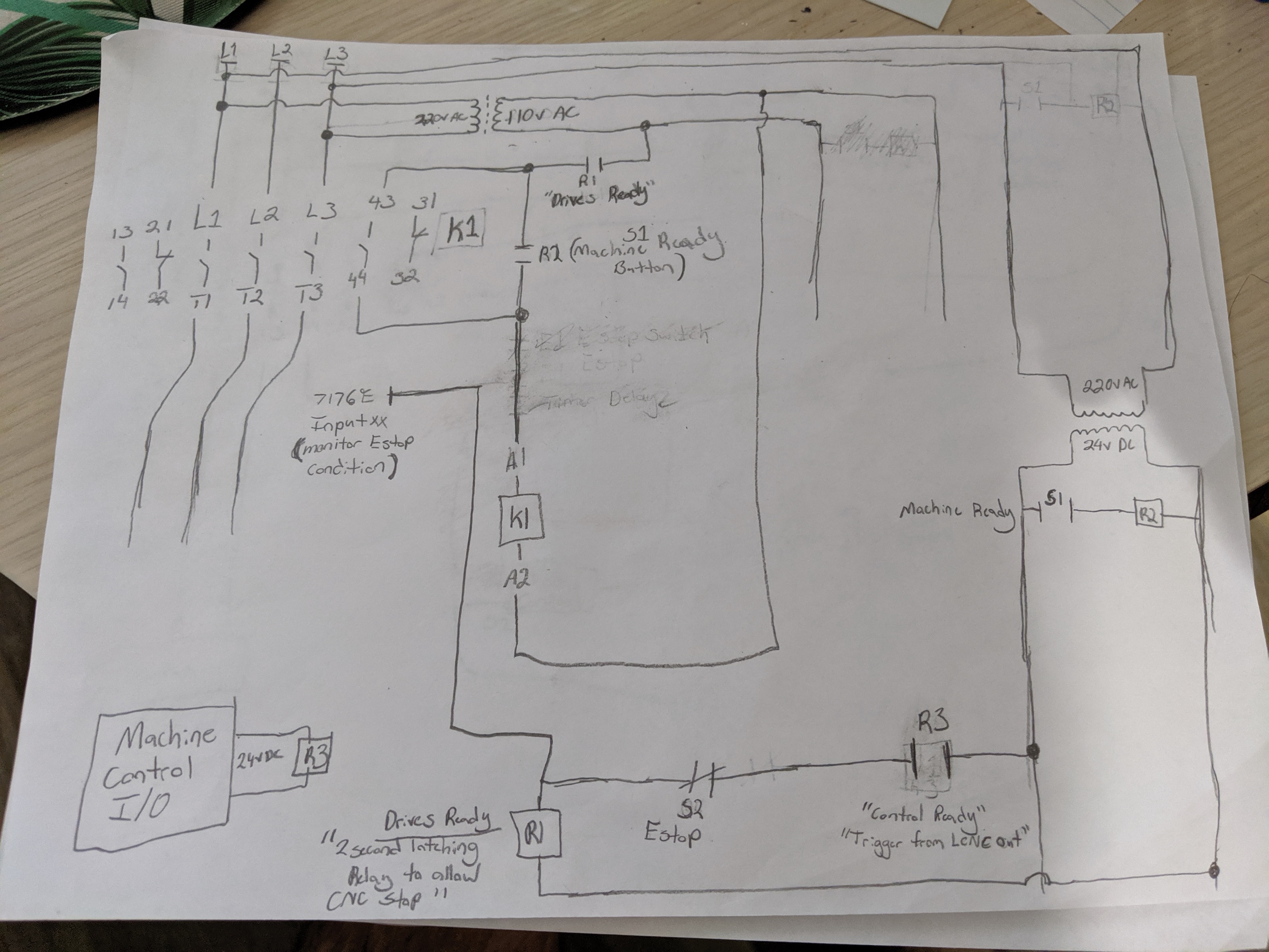
So after thinking about this some more, I've changed my plan to match this schematic.
I'm going to add the latching delayed relay FOR R1 for 1-2 seconds to allow the control the opportunity to give stop command before cutting the power. Which will be triggered by LCNC monitoring the signal at R1. Comanding a stop when the signal drops while R1 holds latched for 2 seconds before breaking K1s power.
Interested to hear feedback on this.
Attachments:
Please Log in or Create an account to join the conversation.
Moderators: PCW, jmelson
Time to create page: 0.130 seconds