ColorCNC Colorlight 5A-75E/5A-75B as FPGA controller board
- ALittleOffTheRails
-

- Visitor
-

18 Feb 2022 21:10 #235279
by ALittleOffTheRails
Replied by ALittleOffTheRails on topic ColorCNC Colorlight 5A-75E/5A-75B as FPGA controller board
The pin mappings are defined in the Litex source, so for the time being I'll assume they are good.
github.com/litex-hub/litex-boards/blob/d...light_5a_75e.py#L200
What I want to know is which is which buffer has which signal on it. The reason being is that I will have to replace some of the buffers to get inputs.
What I intend to do is mod this code github.com/enjoy-digital/colorlite and with a bit of python, gtk and a pin test probe clip work it all out.
Please Log in or Create an account to join the conversation.
- cncwhacko
- Offline
- Junior Member
-

Less
More
- Posts: 33
- Thank you received: 6
18 Feb 2022 22:11 #235289
by cncwhacko
Replied by cncwhacko on topic ColorCNC Colorlight 5A-75E/5A-75B as FPGA controller board
you might be overcomplicating it if thats what you want (locate which buffer each pin belongs to). Im thinking about also replacing some of these at some point but may use parport for inputs and just use this board for outputs and step generation in immediate future.
What I would do is use digital multimeter on continuity test mode on a known pin say, pin 1 on connector J16, have one lead connected to this pin from the multi meter, then sweep remaining lead across the buffer near that connector on bottom side of board, should be pretty easy to locate which buffer has that pin.
One thing to note is that on the J connectors, only pins 1,2,3,5,6,7 are connected to the buffers. the rest of the pins on each connector are 'shared' with the same fpga pins, you can see this in the connector mapping in the file you linked above.
Please Log in or Create an account to join the conversation.
- ALittleOffTheRails
-
- Visitor
-
19 Feb 2022 00:19 - 19 Feb 2022 09:21 #235298
by ALittleOffTheRails
Replied by ALittleOffTheRails on topic ColorCNC Colorlight 5A-75E/5A-75B as FPGA controller board
Yeah I know could sweep the millimeter probe, on a 0.1" pitch I'm okay with that but with a 50 thou pitch not so happy, that's just me & my eye sight. I need to learn some python someday I guess, so I might as well have a go. My son is pretty good at python, part of his physics course at uni, so I'll bend his ear. Plus I can do one buffer in one go.
What you are saying about pins 1,2,3,5,6,7 is a bit misleading (reading it would appear that the common 8 pins are connected to the FPGA without buffers). The A,B,C,D,E,OE,STB,CLK are also connected to buffers, but if they are similar in design to the other boards, 2 connectors share a buffer for those pins.
Considering there are 96 individual pins across all 16 connectors and 8 pins are common across the 16 connectors, giving a total of 104 pins it seems a waste just to use the board for step generation.
My plan is to use 74LVC245 for the inputs, these run on 3.3v but have 5v tolerant inputs, I've used these before on a BoB for my BeagleBone Black.
There is also the option of removing the buffers from the fpga board and bridge the pads with wires and have the buffers on a separate pcb connected via short cables.
Last edit: 19 Feb 2022 09:21 by ALittleOffTheRails. Reason: can't add
Please Log in or Create an account to join the conversation.
- cncwhacko
- Offline
- Junior Member
-
Less
More
- Posts: 33
- Thank you received: 6
21 Feb 2022 01:41 - 21 Feb 2022 01:42 #235439
by cncwhacko
Replied by cncwhacko on topic ColorCNC Colorlight 5A-75E/5A-75B as FPGA controller board
Testing the 5A-75E V8.0 this weekend and have the board flashed with the built file, responding to pings. Linuxcnc loaded with the module successfully, however it seems like the board will stop responding to the etherbone frames after the first exchange. Acts as if it gets overloaded and wedged. At that point, board no longer will respond to pings and has to be reset in order to restore connectivity again. I've noticed romanetz has the etherbone buffer depth set to 1060 bits, however poking around i see github.com/enjoy-digital/liteeth/blob/93...rlight_5a_75b.py#L45 has max set at 255 bits. Is there any implications in going beyond that value?
Frankly not sure what is going on and would appreciate any ideas!
Frankly not sure what is going on and would appreciate any ideas!
Last edit: 21 Feb 2022 01:42 by cncwhacko.
Please Log in or Create an account to join the conversation.
- ALittleOffTheRails
-
- Visitor
-
22 Feb 2022 05:50 - 22 Feb 2022 10:05 #235492
by ALittleOffTheRails
Replied by ALittleOffTheRails on topic ColorCNC Colorlight 5A-75E/5A-75B as FPGA controller board
Sorry not too sure about your issue.
I have started initial investigation into FPGA to Buffer connections for the 5A-75E v7.1. Only J1 to J16 have been done yet.
github.com/ozzyrob/chubby75/blob/master/...V7.1.md#connector-j1
I have started initial investigation into FPGA to Buffer connections for the 5A-75E v7.1. Only J1 to J16 have been done yet.
github.com/ozzyrob/chubby75/blob/master/...V7.1.md#connector-j1
Last edit: 22 Feb 2022 10:05 by ALittleOffTheRails.
Please Log in or Create an account to join the conversation.
- TOLP2
- Offline
- Elite Member
-

Less
More
- Posts: 225
- Thank you received: 178
22 Feb 2022 09:09 #235493
by TOLP2
Replied by TOLP2 on topic ColorCNC Colorlight 5A-75E/5A-75B as FPGA controller board
Why not use a bi-directional level-shifter, for example:
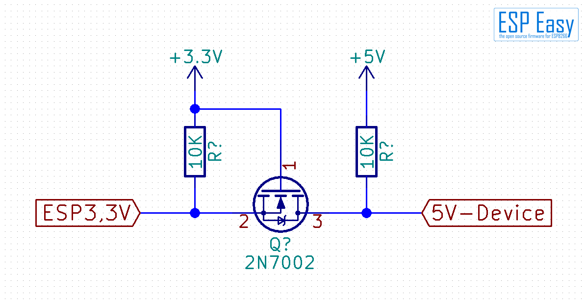
In that case you don't have to use a full block for inputs or outputs.
In that case you don't have to use a full block for inputs or outputs.
Please Log in or Create an account to join the conversation.
- TOLP2
- Offline
- Elite Member
-
Less
More
- Posts: 225
- Thank you received: 178
22 Feb 2022 09:13 #235494
by TOLP2
Replied by TOLP2 on topic ColorCNC Colorlight 5A-75E/5A-75B as FPGA controller board
Also, I'm looking into the possibility to transform the code into a more configurable package based on Litex (so more boards will be supported, as long as they have Ethernet):
- The board should be configurable with a JSON-file where users can define inputs (max 32), outputs (max 32), stepgens and encoders;
- The board-file is build using the Litex recommended toolchain, which also gives the layout of the Etherbone package;
- The configuration-file should also be used by the LinuxCNC component to generate pin-definitions.
Please Log in or Create an account to join the conversation.
- ALittleOffTheRails
-
- Visitor
-
22 Feb 2022 10:11 #235502
by ALittleOffTheRails
You still have to remove the 74HCT245, where the chip was you would have bridge the pads and your circuit would have to be off board.
The 5A-75E V7.1 uses 48 inputs for the GPIOs and Encoders. So to work with that firmware it is far easier to replace a bank of 6 74HCT245 with 6 74LVC245 in a SOIC package. IMHO this seems a simpler solution.
I've used 74LVC245s with another cnc project and they worked very well.
Replied by ALittleOffTheRails on topic ColorCNC Colorlight 5A-75E/5A-75B as FPGA controller board
Why not use a bi-directional level-shifter, for example:
You still have to remove the 74HCT245, where the chip was you would have bridge the pads and your circuit would have to be off board.
The 5A-75E V7.1 uses 48 inputs for the GPIOs and Encoders. So to work with that firmware it is far easier to replace a bank of 6 74HCT245 with 6 74LVC245 in a SOIC package. IMHO this seems a simpler solution.
I've used 74LVC245s with another cnc project and they worked very well.
Please Log in or Create an account to join the conversation.
- TOLP2
- Offline
- Elite Member
-
Less
More
- Posts: 225
- Thank you received: 178
22 Feb 2022 10:43 #235504
by TOLP2
Replied by TOLP2 on topic ColorCNC Colorlight 5A-75E/5A-75B as FPGA controller board
Thanks for your reply!
When you run the chips on 3.3 volt, you have to keep the Vcc pin floating (not connected to the pad, as that will supply 5V) and connect it to 3.3V where it is available on the board?
When you run the chips on 3.3 volt, you have to keep the Vcc pin floating (not connected to the pad, as that will supply 5V) and connect it to 3.3V where it is available on the board?
Please Log in or Create an account to join the conversation.
- ALittleOffTheRails
-
- Visitor
-
22 Feb 2022 11:08 #235508
by ALittleOffTheRails
Replied by ALittleOffTheRails on topic ColorCNC Colorlight 5A-75E/5A-75B as FPGA controller board
Speaking of the 5A-75E V7.1:
There's 3.3v available at J33, (J33,J34) are the power & ground for jtag.
I'm sure if you probed around you could find other points.
Another point worth noting would be adding of a 100n cap for each 74LVC245.
There's 3.3v available at J33, (J33,J34) are the power & ground for jtag.
I'm sure if you probed around you could find other points.
Another point worth noting would be adding of a 100n cap for each 74LVC245.
Please Log in or Create an account to join the conversation.
Moderators: PCW, jmelson
Time to create page: 0.825 seconds