BOB wiring
- Stef
- Offline
- Junior Member
-

Less
More
- Posts: 31
- Thank you received: 2
27 Jun 2023 18:52 #274334
by Stef
BOB wiring was created by Stef
Hi everyone,
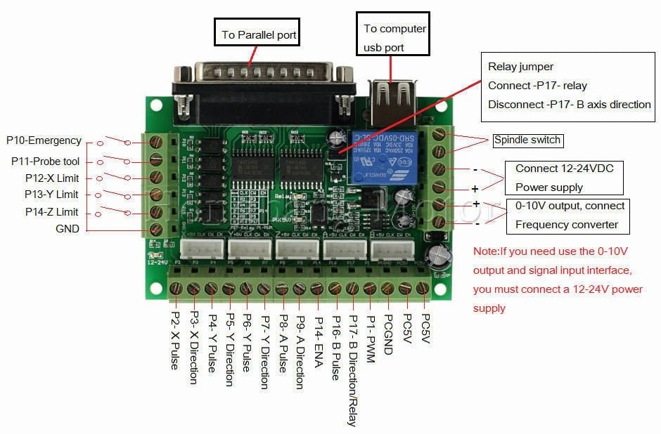
I would like to ask some questions regarding the wiring of the well known Chinese BOB, mostly referred to as something like “5 Axis CNC Breakout board MACH3” (see photo below). I will use this in combination with a Mesa 7C81.
Although some of the questions have been discussed in other topics, I have unfortunately not found a clear answer to them.
The PUL+, DIR+ and ENA+ of each motor drive is wired to the BOB PC5V.
The PUL- and DIR- are wired to the corresponding inputs on the BOB for each axis.
Question 1)
I don’t understand why the ENA- of each axis is connected to the same pin on the BOB.
Perhaps I am misunderstanding, but that means that when the motors are enabled for X or Y movements, the Z axis is automatically also enabled so it will fall down due to gravity. I guess I am wrong because otherwise everyone would run into this issue, but maybe can someone explain this?
Question 2)
To my understanding the USB port is only used to supply 5V to the BOB.
Can I use an external power supply for that? Because I don't want to risk damaging my computer (Raspberry Pi) if something goes wrong in the wiring.
Question 3)
If it is possible to use an external power supply, can that be the same 5V power supply that is used to power the Mesa 7C81? (Actually the Raspberry Pi is also powered via the Mesa card.)
This external 5V power supply shares a common ground with the 48V power supply for the stepper motors and the 24V power supply that is used for both the limit switches and the 24V input on the BOB itself.
Question 4)
It is not clear to me whether or not the BOB GND and the BOB PCGND need to be connected. Although I read about the optocouplers on the BOB, it feels strange to me not to create a common ground.
Any help would be greatly appreciated!
Please Log in or Create an account to join the conversation.
- cakeslob
- Offline
- Platinum Member
-

Less
More
- Posts: 925
- Thank you received: 277
29 Jun 2023 00:54 #274424
by cakeslob
let me dust off the ol breakout card i used when first setting up my 7c81
Q1 - ENA is connected to all axis, so stepper drivers are turned on all at the same time, usually with machine power button. Its probably to save on i/o pins. Im not understanding exactly what you mean, but the opposite, since all axis are enabled, you would not fall on z.
q2 - yeah, go for it, should be fine
Q3 - Based on these wires, I was using GND for 12v and 5v at the time, I dont know if thats kosher or not but it looks like thats what I was doing
Q4 - I dont think I was using PCGND for anything, but you need GND for the optos
Replied by cakeslob on topic BOB wiring
Hi everyone,
I would like to ask some questions regarding the wiring of the well known Chinese BOB, mostly referred to as something like “5 Axis CNC Breakout board MACH3” (see photo below). I will use this in combination with a Mesa 7C81.
Although some of the questions have been discussed in other topics, I have unfortunately not found a clear answer to them.
The PUL+, DIR+ and ENA+ of each motor drive is wired to the BOB PC5V.
The PUL- and DIR- are wired to the corresponding inputs on the BOB for each axis.
Question 1)
I don’t understand why the ENA- of each axis is connected to the same pin on the BOB.
Perhaps I am misunderstanding, but that means that when the motors are enabled for X or Y movements, the Z axis is automatically also enabled so it will fall down due to gravity. I guess I am wrong because otherwise everyone would run into this issue, but maybe can someone explain this?
Question 2)
To my understanding the USB port is only used to supply 5V to the BOB.
Can I use an external power supply for that? Because I don't want to risk damaging my computer (Raspberry Pi) if something goes wrong in the wiring.
Question 3)
If it is possible to use an external power supply, can that be the same 5V power supply that is used to power the Mesa 7C81? (Actually the Raspberry Pi is also powered via the Mesa card.)
This external 5V power supply shares a common ground with the 48V power supply for the stepper motors and the 24V power supply that is used for both the limit switches and the 24V input on the BOB itself.
Question 4)
It is not clear to me whether or not the BOB GND and the BOB PCGND need to be connected. Although I read about the optocouplers on the BOB, it feels strange to me not to create a common ground.
Any help would be greatly appreciated!
let me dust off the ol breakout card i used when first setting up my 7c81
Q1 - ENA is connected to all axis, so stepper drivers are turned on all at the same time, usually with machine power button. Its probably to save on i/o pins. Im not understanding exactly what you mean, but the opposite, since all axis are enabled, you would not fall on z.
q2 - yeah, go for it, should be fine
Q3 - Based on these wires, I was using GND for 12v and 5v at the time, I dont know if thats kosher or not but it looks like thats what I was doing
Q4 - I dont think I was using PCGND for anything, but you need GND for the optos
Please Log in or Create an account to join the conversation.
- Stef
- Offline
- Junior Member
-
Less
More
- Posts: 31
- Thank you received: 2
05 Jul 2023 21:40 - 05 Jul 2023 21:41 #274852
by Stef
Replied by Stef on topic BOB wiring
Thank you very much Cakeslob! Your input gave me the confidence to power up my system, and it works perfectly. After months of preparations it was very satisfying to see the motors running for the first time.
The next step is to use the home sensors. I have connected the home-x sensor to P12 of the BOB.
According to the Mesa 7C81 manual , pin 12 of the DB25 connector is connected to IO15. If I understand this correctly, the HAL file should contain this line:
net home-x <= [HMOT](CARD0).gpio.015.in
Although the sensor itself is working properly (it has an integrated LED), the motor does not stop homing when the sensor is activated, so somehow LinuxCNC does not recognize the sensor input. Maybe am I missing something?
Last edit: 05 Jul 2023 21:41 by Stef.
Please Log in or Create an account to join the conversation.
- tommylight
-

- Offline
- Moderator
-

Less
More
- Posts: 21619
- Thank you received: 7383
05 Jul 2023 21:50 #274853
by tommylight
Replied by tommylight on topic BOB wiring
It should also have
net home-x => joint.0.home-sw-in
And other lines if that same switch is used as limit switch.
net home-x => joint.0.home-sw-in
And other lines if that same switch is used as limit switch.
Please Log in or Create an account to join the conversation.
- Stef
- Offline
- Junior Member
-
Less
More
- Posts: 31
- Thank you received: 2
05 Jul 2023 22:20 #274861
by Stef
Replied by Stef on topic BOB wiring
That was a very quick reply ")
The line that you mentioned is also in the HAL file (actually I just hadn't noticed it before as the file was not created by myself but with the Pncconf wizard).
So I think that something else is wrong, perhaps it does not have anything to do with the HAL file.
The line that you mentioned is also in the HAL file (actually I just hadn't noticed it before as the file was not created by myself but with the Pncconf wizard).
So I think that something else is wrong, perhaps it does not have anything to do with the HAL file.
Please Log in or Create an account to join the conversation.
- tommylight
-
- Offline
- Moderator
-
Less
More
- Posts: 21619
- Thank you received: 7383
05 Jul 2023 22:52 #274865
by tommylight
Replied by tommylight on topic BOB wiring
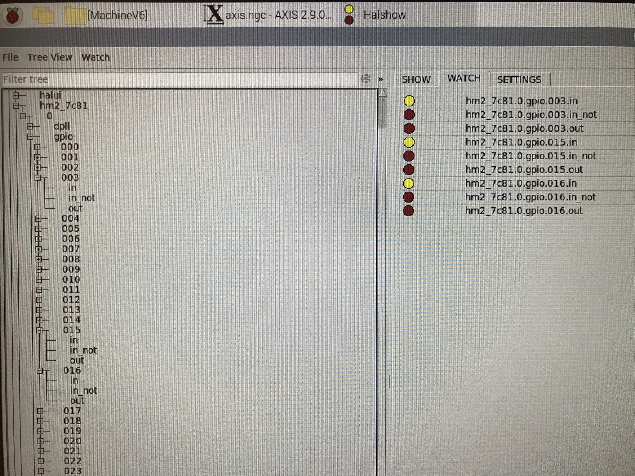
Use the "show hal configuration" from the "machine" menu, on the right side choose "watch", on the left side navigate to "pins" and find the mesa input pin, click on it.
Now on the right side watch the LED if it changes color while you manually activate the sensor.
Now on the right side watch the LED if it changes color while you manually activate the sensor.
Please Log in or Create an account to join the conversation.
- Stef
- Offline
- Junior Member
-
Less
More
- Posts: 31
- Thank you received: 2
12 Jul 2023 20:58 #275299
by Stef
Replied by Stef on topic BOB wiring
Thank you for the advice, today I had the chance to try it out.
I have connected a limit switch to pin 12, 13 and 15 (not simultaneously), but although the LED on the limit switch itself changes color, none of the LEDs in the "Show HAL configuration" window (see screenshot) changed color.
Both the limit switch and the BOB are powered with 24V. I am pretty sure that all the wiring is right, so it is difficult for me to understand where to look for the problem unfortunately.
Attachments:
Please Log in or Create an account to join the conversation.
- tommylight
-
- Offline
- Moderator
-
Less
More
- Posts: 21619
- Thank you received: 7383
12 Jul 2023 21:09 #275300
by tommylight
Replied by tommylight on topic BOB wiring
Upload the hal and ini file here so we can have a look.
Please Log in or Create an account to join the conversation.
- Stef
- Offline
- Junior Member
-
Less
More
- Posts: 31
- Thank you received: 2
12 Jul 2023 21:42 #275304
by Stef
Replied by Stef on topic BOB wiring
Please find attached the hal and ini file, I would be very interested to hear if this contains anything strange.
Please Log in or Create an account to join the conversation.
- PCW
-

- Offline
- Moderator
-
Less
More
- Posts: 17916
- Thank you received: 5245
12 Jul 2023 21:56 #275305
by PCW
Replied by PCW on topic BOB wiring
Do you have 5V power supplied to the BOB?
Can you check the signal at the BOB DB25 pins?
Can you check the signal at the BOB DB25 pins?
Please Log in or Create an account to join the conversation.
Moderators: PCW, jmelson
Time to create page: 0.761 seconds