BOB wiring

More
3 years 3 months ago #275299 by Stef
Replied by Stef on topic BOB wiring
Thank you for the advice, today I had the chance to try it out.
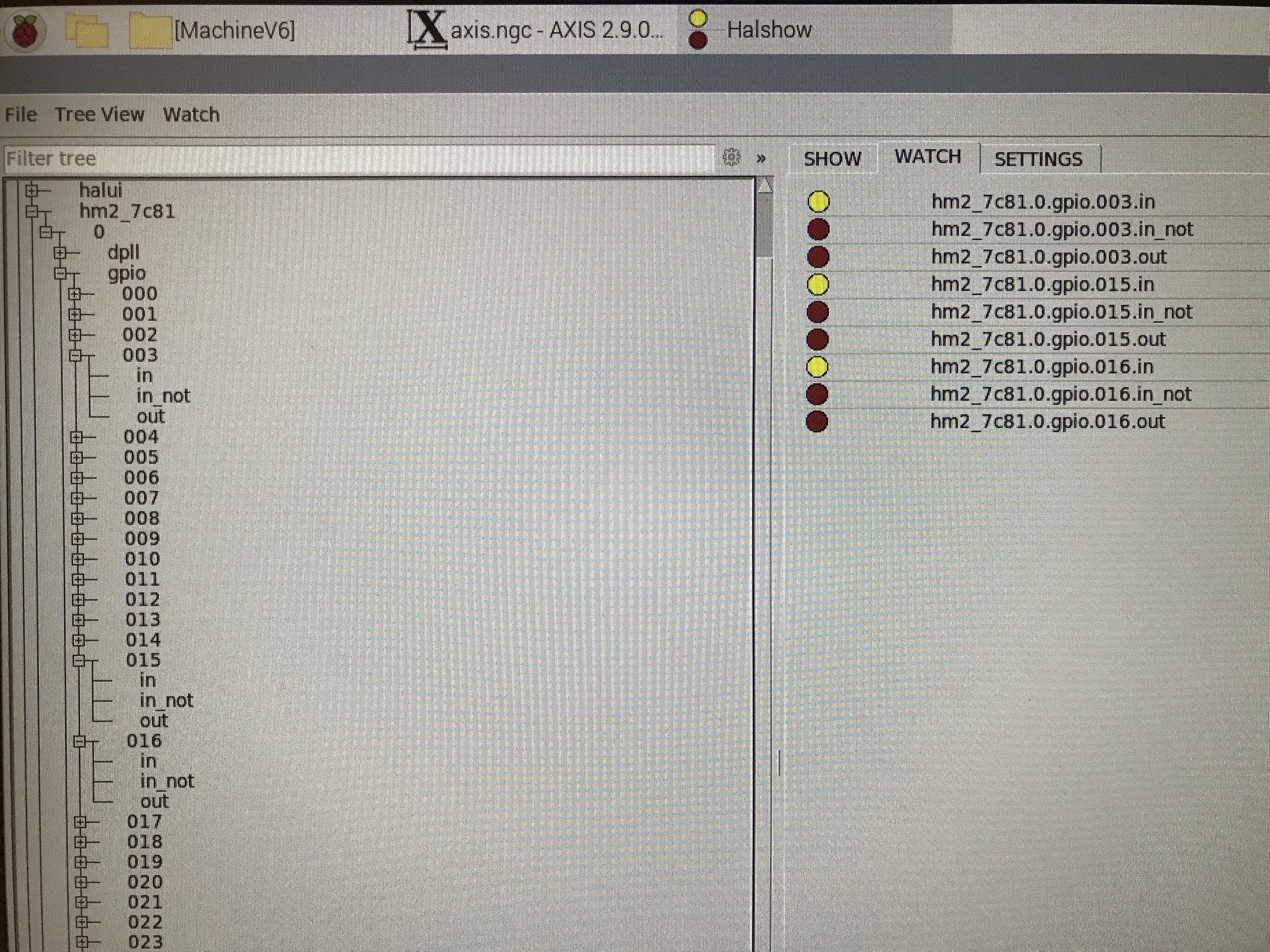
I have connected a limit switch to pin 12, 13 and 15 (not simultaneously), but although the LED on the limit switch itself changes color, none of the LEDs in the "Show HAL configuration" window (see screenshot) changed color.
Both the limit switch and the BOB are powered with 24V. I am pretty sure that all the wiring is right, so it is difficult for me to understand where to look for the problem unfortunately.


Please Log in or Create an account to join the conversation.

More
3 years 3 months ago #275300 by tommylight
Replied by tommylight on topic BOB wiring
Upload the hal and ini file here so we can have a look.

Please Log in or Create an account to join the conversation.

More
3 years 3 months ago #275304 by Stef
Replied by Stef on topic BOB wiring
Please find attached the hal and ini file, I would be very interested to hear if this contains anything strange.

Please Log in or Create an account to join the conversation.

More
3 years 3 months ago #275305 by PCW
Replied by PCW on topic BOB wiring
Do you have 5V power supplied to the BOB?

Can you check the signal at the BOB DB25 pins?

Please Log in or Create an account to join the conversation.

More
3 years 3 months ago #275374 by Stef
Replied by Stef on topic BOB wiring
With the BOB connected to the Mesa card, I measured the voltage between HDR26 pin 10 and pin 23 (via the soldered pins on the underside of the Mesa card).
This is 5V, and activating the limit switch does not change this voltage. The limit switch is connected to pin 12 of the BOB.
With the BOB completely disconnected from the Mesa card I still measure this 5V between HDR26 pin 10 and pin 23.


The BOB is supplied with 5V.
I attached some images, just to show my test setup. The colors of the wires correspond to:

Black: GND
White: 5V
Yellow: 24V
Red: 48V

Orange: PUL-
Green: DIR-
Purple: ENA-


Please Log in or Create an account to join the conversation.

More
3 years 3 months ago #275380 by PCW
Replied by PCW on topic BOB wiring
Something with the switch wiring?
The BOB input circuitry is really simple:

+12/24V to all OPTO LED Anodes
OPTO LED Cathodes --> 1K resistor --> terminal block Input pins

All OPTO transistor emitters grounded
OPTO transistor collectors to DB25 pins 10,11,12,13,15

(so they depend on external pullups which should be OK since the
7C81 has 3.3K pullips on all I/O pins)

Please Log in or Create an account to join the conversation.

Moderators: PCW, jmelson
Time to create page: 0.306 seconds
Powered by Kunena Forum