Will a Mesa 7i96s work in my case?
- PCW
-

- Offline
- Moderator
-

- Posts: 17867
- Thank you received: 5232
The step pulses at P1 should be positive, of the programmed length and ~3.3V
Note, P1 pin number are not the same as DB25 pin numbers (as listed in the Mach setup screen)
so make sure you keep this in mind if checking at the 7I96S and not the DB25 cable.
If you don't get pulses at the Geckos, maybe the wiring does not match what you expect
This may be something that needs to be traced.
I would expect the tuning routine to block access by other programs
to the card just as LinuxCNC does when it is running running.
Have you tried an actual LinuxCNC test?
Please Log in or Create an account to join the conversation.
- PCW
-
- Offline
- Moderator
-
- Posts: 17867
- Thank you received: 5232
with a 5 usec (5000 ns) step time selected:

Attachments:
Please Log in or Create an account to join the conversation.
- hpeyerl
-
 Topic Author
- Visitor
-

Well, there are no negative voltages so perhaps you have the wrong ground reference.
Perhaps. I was clipped onto a pin on the JTAG connector that appeared to attach to the ground plane (pin 9 I think). I was getting noise when clipped to one of the plated screw holes.
Note, P1 pin number are not the same as DB25 pin numbers (as listed in the Mach setup screen) so make sure you keep this in mind if checking at the 7I96S and not the DB25 cable.
oh. This may be my problem. I hadn't noted the table on p.7 of the 7i96sman.pdf which cross references P1 pin to DB25 pin. I saw the text above that says P1 has a pin-out that matches standard parallel port breakout cards but didn't look at the table. The 26 pin IDC on my controller box does normally have a 1:1 ribbon cable to the DB25 on the back of the box. So clearly I can't use a 1:1 26 pin ribbon cable to connect P1 to the 26 pin IDC on my controller. I'll need to re-arrange that cable and thus, I wonder if I should just go to TB1/TB2 instead.
I would expect the tuning routine to block access by other programs to the card just as LinuxCNC does when it is running running.
I meant that once I start the tuning routine, I can no longer ping the LinuxCNC IP address (and icmp is handled inside the Linux kernel). As soon as I stop the tuning routine, the Linux kernel begins to respond to pings again.
Have you tried an actual LinuxCNC test?
Nope. I'm definitely not that smart yet.
Please Log in or Create an account to join the conversation.
- PCW
-
- Offline
- Moderator
-
- Posts: 17867
- Thank you received: 5232
its 26 pin header should match. That is, if I use a 1-1 flat cable
HDR26 --> DB25 from the 7I96S Expansion connector, the DB25 end
will match a normal parallel port pinout. (For example DB25 pin 2
will be Step0)
Please Log in or Create an account to join the conversation.
- hpeyerl
-
Topic Author
- Visitor
-
So ok, I'm glad my cable is theoretically fine. When I built it, I ensured that P1:1 mated with Pin 1 on the controller (there is a symbol on the solder mask of the controller which matches with Pin 1 of the DB-25 cable assembly that was previously connected). Unless the '1' symbol on the solder mask is actually pin 2 and thus connects to pin 14 of the DB-25. I'll check that next time I get in front of it.
Please Log in or Create an account to join the conversation.
- hpeyerl
-
Topic Author
- Visitor
-
Checking further, looks like I have no Vcc at the SN74ACT14's.
So that would be the smoking gun. sigh. That's the end of my fun-time for the day.
Please Log in or Create an account to join the conversation.
- hpeyerl
-
Topic Author
- Visitor
-
Anyway, I cut 18/20/22/24/26 and now all of my steppers move (albeit crappily but now I can tune them).
Please Log in or Create an account to join the conversation.
- PCW
-
- Offline
- Moderator
-
- Posts: 17867
- Thank you received: 5232
as a PC parallel port has DB25 pins 18 through 25
(HDR26 pins 10,12,14,16,18,20,22,24) grounded
Please Log in or Create an account to join the conversation.
- hpeyerl
-
Topic Author
- Visitor
-
Final step was to power the board from inside the old controller chassis instead of my bench supply. I wasn't really thinking clearly (See: Covid) when I found the 30V supply to my Geckos and wired it to the 5V connector on the 7i96s.
So, what do you think the chances are that I blew only CR43 and nothing further down the line? Doesn't look like any toasted traces. C66 is probably implicated as well.
I can do the rework if I know what the part is.
I am my own worst enemy sometimes.
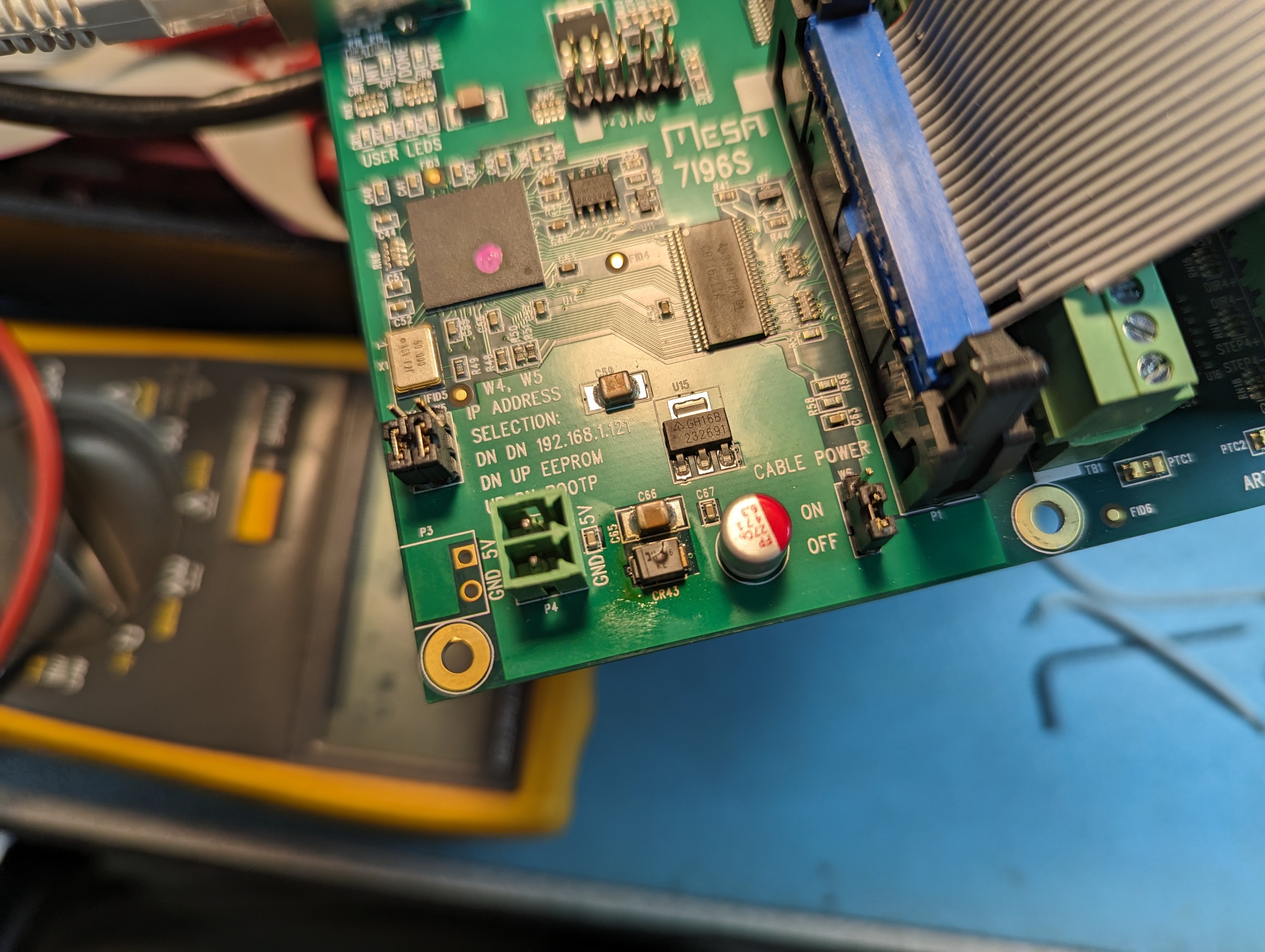
Attachments:
Please Log in or Create an account to join the conversation.
- PCW
-
- Offline
- Moderator
-
- Posts: 17867
- Thank you received: 5232
Typically this would be the only failed component, unless
you plugged the 30V in hot so the current spike was huge.
Please Log in or Create an account to join the conversation.