IC Replacement
- Estero
-
 Topic Author
- Offline
- New Member
-

Less
More
- Posts: 4
- Thank you received: 1
30 Jan 2024 08:02 - 30 Jan 2024 08:04 #291959
by Estero
IC Replacement was created by Estero
Hello. This question is most likely for Mr. Wallace, I assume.
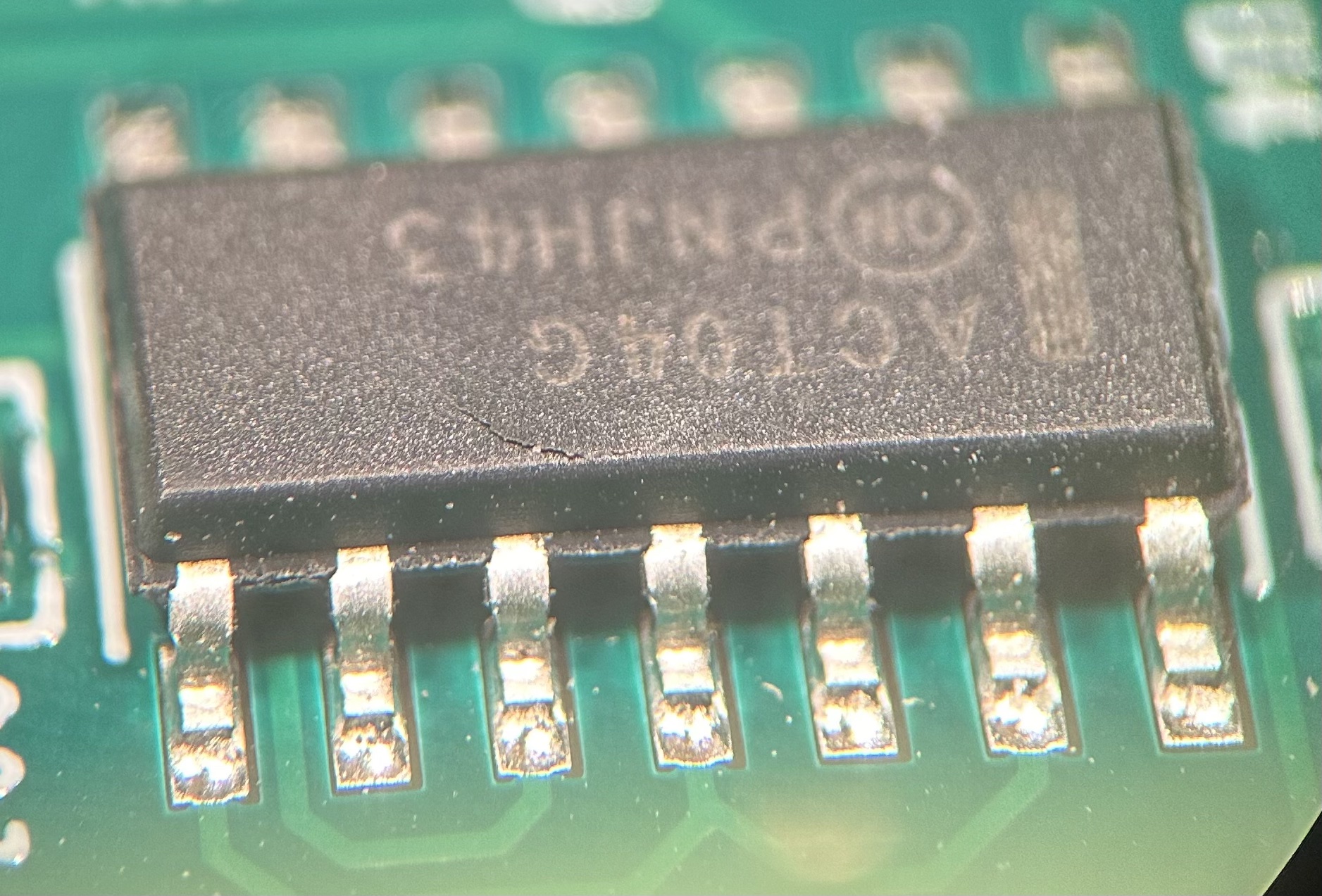
Having connected my 7i89 board to my 7i76e board using an (apparently) miswired DB25M to IDC26 cable, I seem to have blown the top off what I believe is a hex inverter:
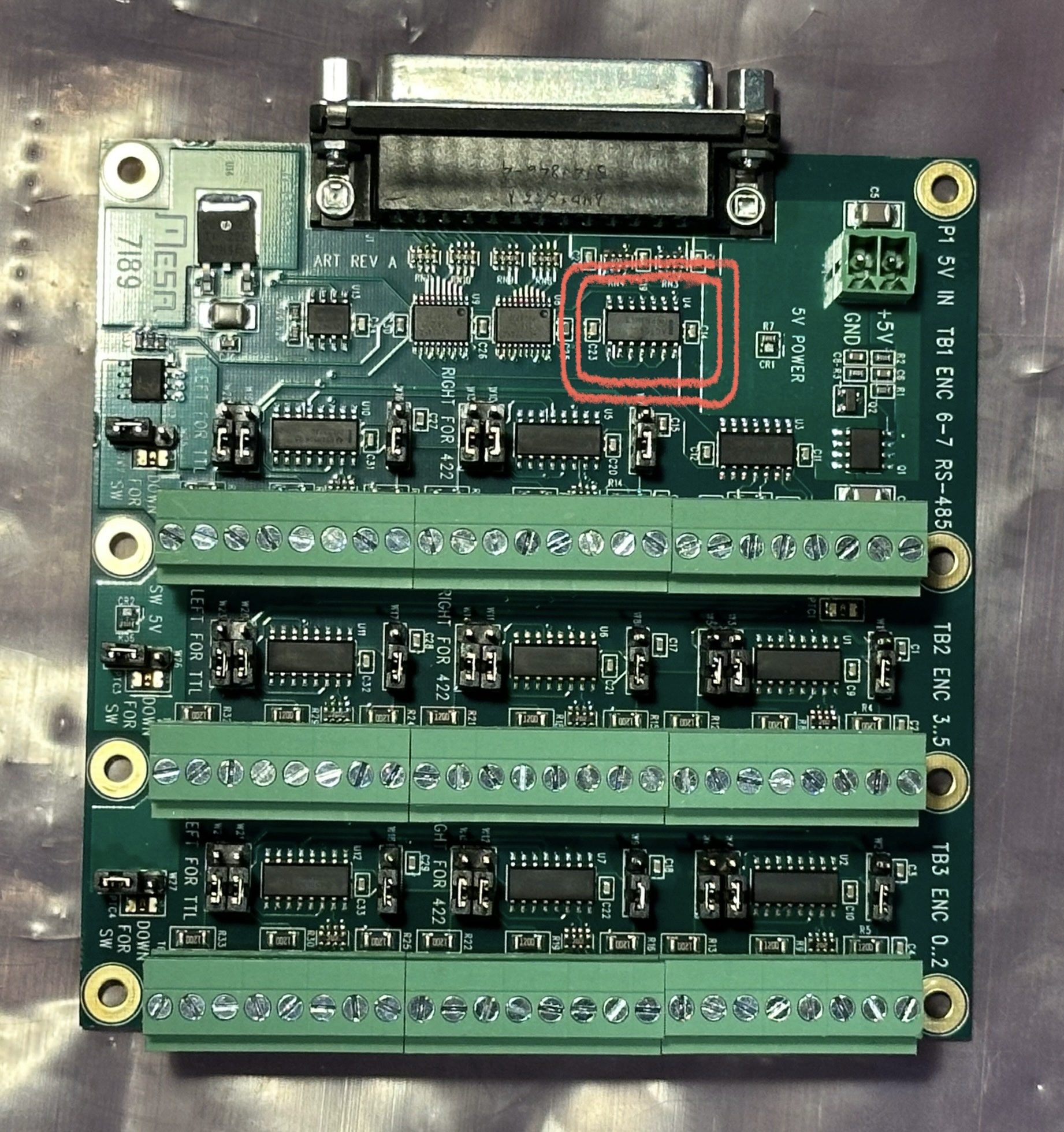
I intend to try to fix it.
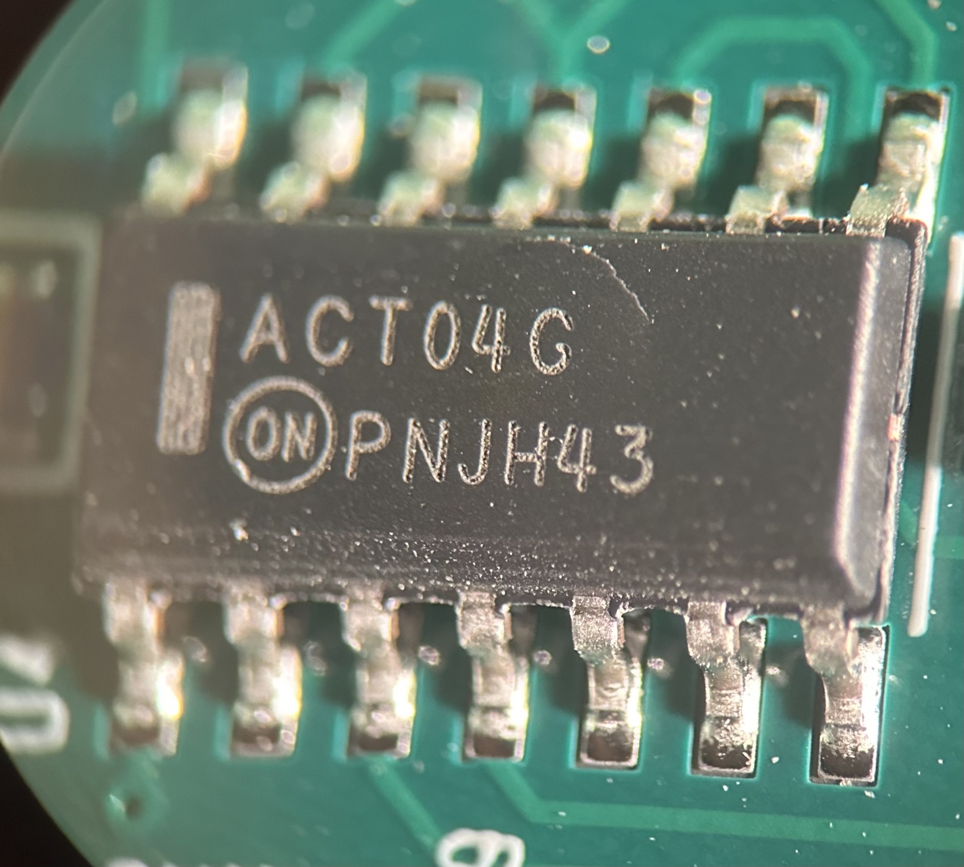
I can't find an ON Semiconductor record for a chip exactly identified as "ACT04G." Perhaps this 74ACT04SCX is a close enough match?:
74AC04, 74ACT04 Data Sheet
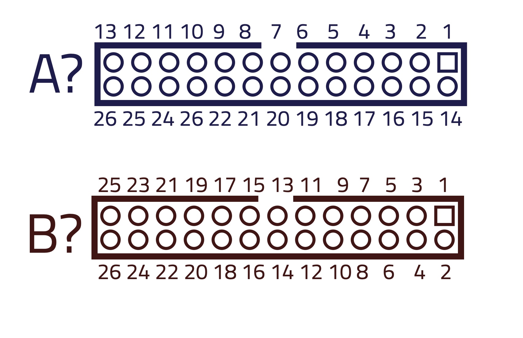
Lastly, I think my mistake was in assuming I understood the pin numbering on the 7i76e's expansion connectors. Which of these (or neither) is correct?:
Thanks in advance!
Having connected my 7i89 board to my 7i76e board using an (apparently) miswired DB25M to IDC26 cable, I seem to have blown the top off what I believe is a hex inverter:
I intend to try to fix it.
I can't find an ON Semiconductor record for a chip exactly identified as "ACT04G." Perhaps this 74ACT04SCX is a close enough match?:
74AC04, 74ACT04 Data Sheet
Lastly, I think my mistake was in assuming I understood the pin numbering on the 7i76e's expansion connectors. Which of these (or neither) is correct?:
Thanks in advance!
Attachments:
Last edit: 30 Jan 2024 08:04 by Estero. Reason: Hyperlink Format
Please Log in or Create an account to join the conversation.
- vre
- Offline
- Platinum Member
-

Less
More
- Posts: 610
- Thank you received: 17
30 Jan 2024 15:17 #291986
by vre
Replied by vre on topic IC Replacement
Yes it is hex inverter.
The correct pinout is B.
A is wrong.
The correct pinout is B.
A is wrong.
Please Log in or Create an account to join the conversation.
- Cant do this anymore bye all
-

- Offline
- Platinum Member
-
Less
More
- Posts: 1200
- Thank you received: 425
30 Jan 2024 21:40 - 30 Jan 2024 21:46 #292022
by Cant do this anymore bye all
Replied by Cant do this anymore bye all on topic IC Replacement
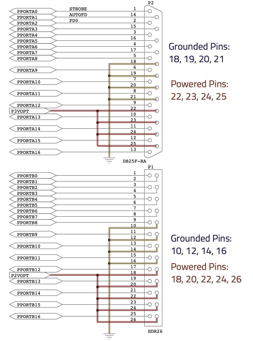
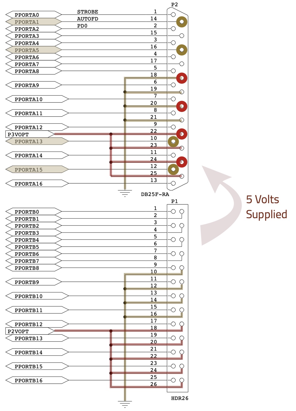
This might make it a bit clearer, 7i92 schematic but pinouts are the same for all boards.
Shows both the header and db-25 numbering.
Actually form 'A' is the more correct form, as the header is the same electrically (signal wise) as the Parallel Port header on a PC.
Shows both the header and db-25 numbering.
Actually form 'A' is the more correct form, as the header is the same electrically (signal wise) as the Parallel Port header on a PC.
Attachments:
Last edit: 30 Jan 2024 21:46 by Cant do this anymore bye all.
Please Log in or Create an account to join the conversation.
- PCW
-

- Offline
- Moderator
-

Less
More
- Posts: 17917
- Thank you received: 5246
30 Jan 2024 21:48 - 30 Jan 2024 21:49 #292023
by PCW
Replied by PCW on topic IC Replacement
Actually both a A and B are correct.
B shows standard 26 pin header pinout
and A shows the equivalent DB25 pins.
with a standard IDC cable.
The correct pinout cable is created by using
a IDC 26 female header and a IDC DB25,
Crimped onto a flat cable, pin 1 to pin 1.
B shows standard 26 pin header pinout
and A shows the equivalent DB25 pins.
with a standard IDC cable.
The correct pinout cable is created by using
a IDC 26 female header and a IDC DB25,
Crimped onto a flat cable, pin 1 to pin 1.
Last edit: 30 Jan 2024 21:49 by PCW.
Please Log in or Create an account to join the conversation.
- Estero
-
Topic Author
- Offline
- New Member
-
Less
More
- Posts: 4
- Thank you received: 1
31 Jan 2024 06:16 #292047
by Estero
Replied by Estero on topic IC Replacement
So I think I'm discovering that besides Pin 1 the actual pin numbers from the mother card to the daughter card aren't actually intended to link up. Here's what I mean:
In both cases the 5V power and ground channels are all in a row on the left side of the connector (as pictured). But the respective pin numbers are different.
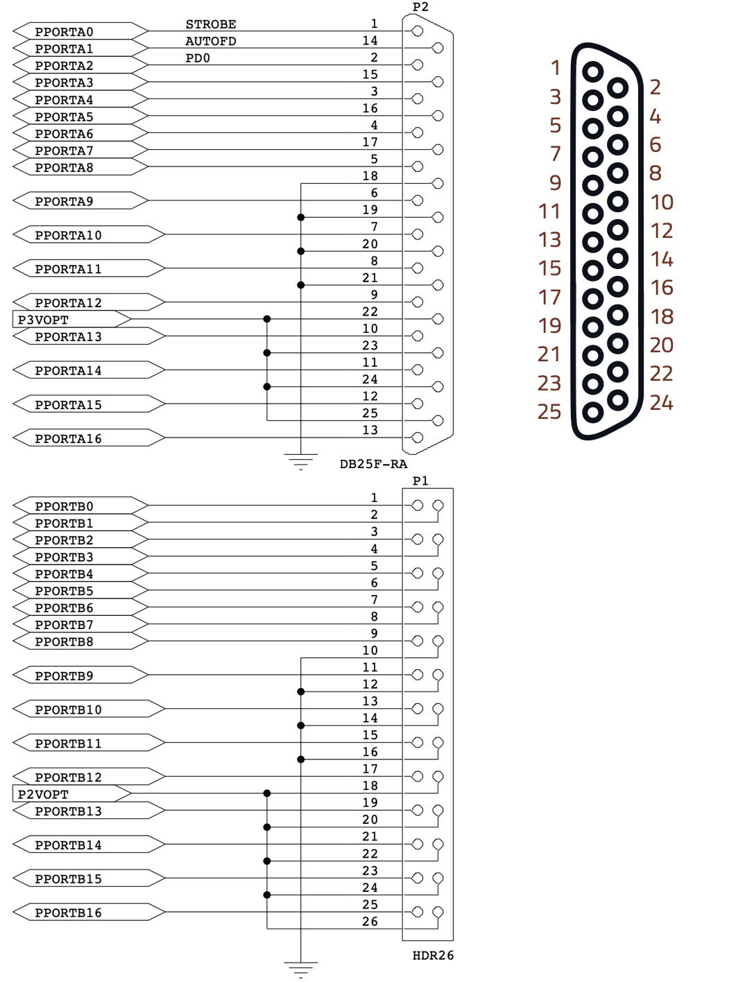
Actually, both the header and the DB25 connector have an "odds on one side, evens on the other side" configuration, right? More like so:
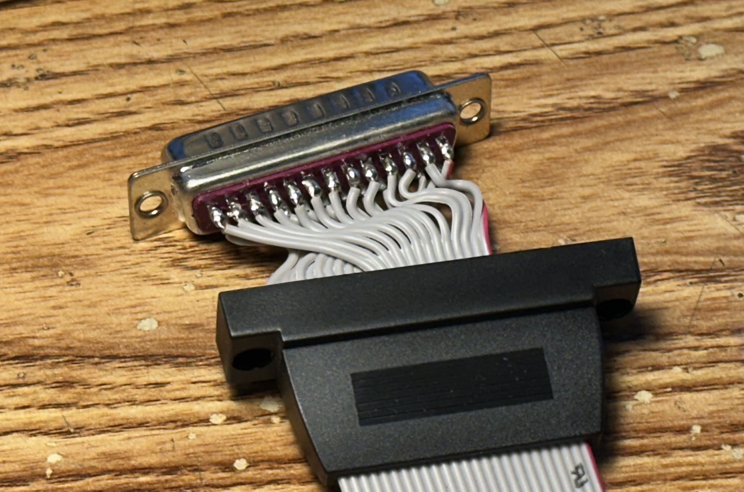
I understand now about making sure to use crimp connectors as this mechanically sorts this out. So this cord is not appropriate with 1-13 on the top row and 14-25 on the bottom row:
In the meantime I've ordered the cable from Mesa just to be 100% certain. Now I just need to figure out what damage I did, exactly, to the card. It looks to me like I mixed 5V power and ground in a few places and grounded the following pins (assuming the 7i92 graphic matches):
PPORTA 1
PPORTA 5
PPORTA 13
PPORTA 15
PPORTA 13 (Daughter Card Pin #10) has continuity up to the damaged IC. I suppose I'll let that confirm my suspicion. I'll order the chip I linked to in the original post, plus anything else anyone suggests. (Side note: I also tried this with a used 7i85 I got from eBay and I disconnected it when one of the chips felt warm. It still lights up when connected through P1 whereas the 7i89 does not.) Wish me luck; I'll replace it with a new one as a last resort. Thanks for your replies.
In both cases the 5V power and ground channels are all in a row on the left side of the connector (as pictured). But the respective pin numbers are different.
Actually, both the header and the DB25 connector have an "odds on one side, evens on the other side" configuration, right? More like so:
I understand now about making sure to use crimp connectors as this mechanically sorts this out. So this cord is not appropriate with 1-13 on the top row and 14-25 on the bottom row:
In the meantime I've ordered the cable from Mesa just to be 100% certain. Now I just need to figure out what damage I did, exactly, to the card. It looks to me like I mixed 5V power and ground in a few places and grounded the following pins (assuming the 7i92 graphic matches):
PPORTA 1
PPORTA 5
PPORTA 13
PPORTA 15
PPORTA 13 (Daughter Card Pin #10) has continuity up to the damaged IC. I suppose I'll let that confirm my suspicion. I'll order the chip I linked to in the original post, plus anything else anyone suggests. (Side note: I also tried this with a used 7i85 I got from eBay and I disconnected it when one of the chips felt warm. It still lights up when connected through P1 whereas the 7i89 does not.) Wish me luck; I'll replace it with a new one as a last resort. Thanks for your replies.
Attachments:
Please Log in or Create an account to join the conversation.
- Cant do this anymore bye all
-
- Offline
- Platinum Member
-
Less
More
- Posts: 1200
- Thank you received: 425
31 Jan 2024 09:35 #292056
by Cant do this anymore bye all
Replied by Cant do this anymore bye all on topic IC Replacement
Easiest way is to use a 26 pin IDC female connector to DB-25 IDC connector.
DB25 connectors (male or female) have 1-13 on the top row, 14-25 on the bottom row. Pin 26 is not connected.
On the IDC box header (as numbered on a LPT header), 1 - 13 are on the "keyed" side and 14-26 are on the non-keyed side, when connecting to a DB-25 connector.
Looking at a 26 way flat ribbon cable,
The wire with the red or black tracer is 1 goes to pin 1 on the DB-25 connector,
the 2nd wire goes to pin 14 of the DB-25 connector,
the 3rd wire goes to pin 2 on the DB-25 connector,
the 4th wire goes to pin 15 on the DB-25 connector,
the 5th wire goes to pin 3 DB-25 connector,
the 6th wire goes to pin 16 on the DB-25 connector and so on.
Grab a multimeter and buzz out the connections.
Please Log in or Create an account to join the conversation.
Moderators: PCW, jmelson
Time to create page: 0.594 seconds