

- Posts: 189
- Thank you received: 44
1982 Matsuura MC-500v Retrofit
9 years 8 months ago - 9 years 8 months ago #87827
by chopper79
Replied by chopper79 on topic 1982 Matsuura MC-500v Retrofit
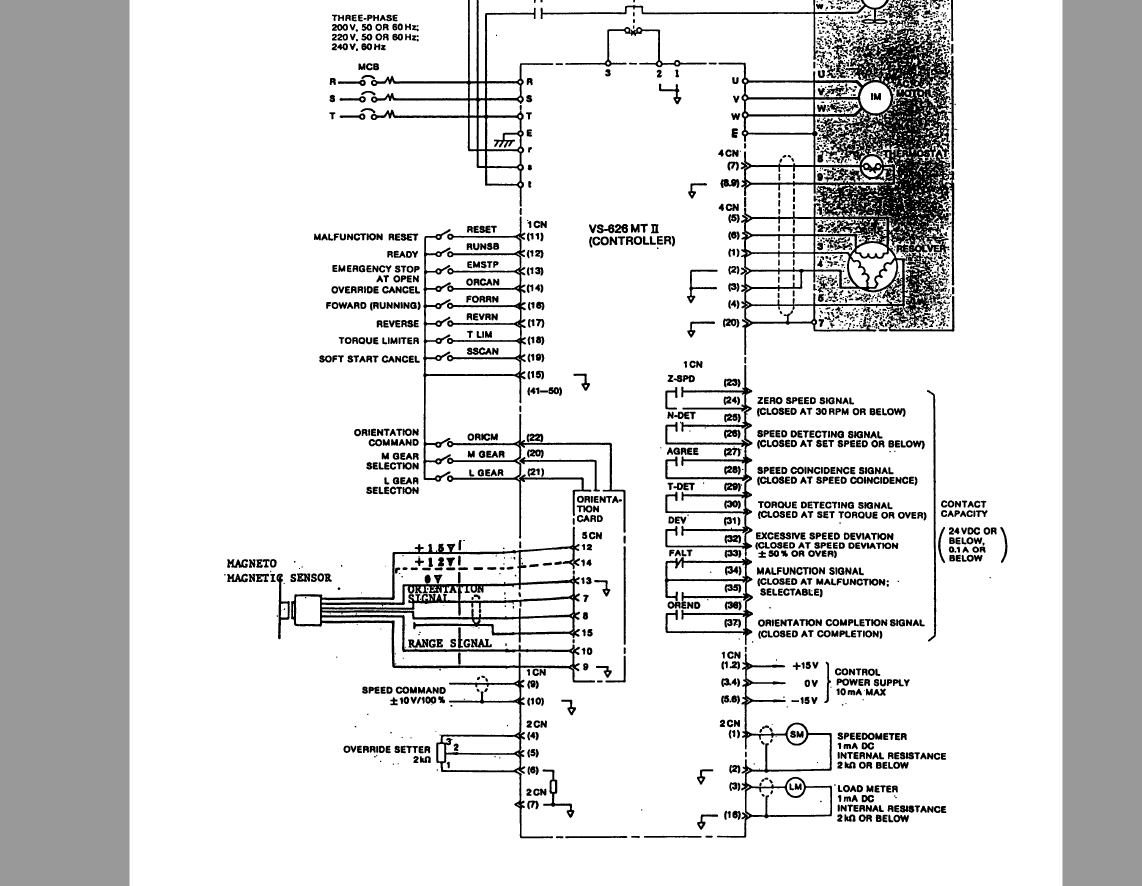
Working on getting my spindle running. I am hesitant to connect some of the signal wires. I know I need the following:
Inputs
Pin 9 = Speed command +/- 10v
Pin 10 = Signal ground
Pin 12 = Ready
Pin 15 = Signal ground
Pin 16 = FWD run
Pin 17 = REV run
Pin 22 = Spindle Orientation
My mind is not allowing me to come to a definite answer on if I should take 24vdc + to the pins to close the contact (excluding signal ground pins and speed control pins). Should I?
I normally do not have issues reading a schematic, but today I am. Also I am a little worried about burning up an expensive part like a VFD. Gun shy I guess.... Any help the connections would be wonderful.
Inputs
Pin 9 = Speed command +/- 10v
Pin 10 = Signal ground
Pin 12 = Ready
Pin 15 = Signal ground
Pin 16 = FWD run
Pin 17 = REV run
Pin 22 = Spindle Orientation
My mind is not allowing me to come to a definite answer on if I should take 24vdc + to the pins to close the contact (excluding signal ground pins and speed control pins). Should I?
I normally do not have issues reading a schematic, but today I am. Also I am a little worried about burning up an expensive part like a VFD. Gun shy I guess.... Any help the connections would be wonderful.
Last edit: 9 years 8 months ago by chopper79.
Please Log in or Create an account to join the conversation.
9 years 8 months ago #87829
by PCW
Replied by PCW on topic 1982 Matsuura MC-500v Retrofit
Looks like the pins are switched to ground to enable
24V applied to any of those pins is likely to damage the drive
24V applied to any of those pins is likely to damage the drive
The following user(s) said Thank You: chopper79
Please Log in or Create an account to join the conversation.
9 years 8 months ago - 9 years 8 months ago #87830
by chopper79
Replied by chopper79 on topic 1982 Matsuura MC-500v Retrofit
Just seen this.... I was starting to lean towards ground after looking at it some more. I will give it a shot and see if I can at least get the fwd led to illuminate.
Thank you PCW
***Update on spindle drive***
If you have the Yaskawa VS-626 MTII on your machine (Matsuura MC-500v2) then you will need the following:
Pins on connector 1CN
Pin 9 = Analog speed control +/- 10v
Pin 10 = Analog speed control gnd
Pin 13 = Estop
Pin 15 = Signal ground
Pin 16 = Spindle forward
Pin 17 = Spindle reverse
Pin 22 = Spindle orientation command
Pin 15 (signal ground) need to be closed to the pin needed. Such as 7i77 24v+ output goes to a relay and the relay closes the connection from pin 15 to pin needed on VFD. The VFD pins take a ground input not + voltage
Pins 9 and 10 will go to the spindle output designated on the 7i77. The 7i77 will drive these directly.
Also do not over look the outputs on the VFD.
At speed output (Just nice to have so LCNC knows that spindle is at requested speed)
Orientation complete output (need for ATC)
There are other outputs that could be handy also if used.
See previous posts for all manuals and schematics of factory wiring and components.
Thank you PCW
***Update on spindle drive***
If you have the Yaskawa VS-626 MTII on your machine (Matsuura MC-500v2) then you will need the following:
Pins on connector 1CN
Pin 9 = Analog speed control +/- 10v
Pin 10 = Analog speed control gnd
Pin 13 = Estop
Pin 15 = Signal ground
Pin 16 = Spindle forward
Pin 17 = Spindle reverse
Pin 22 = Spindle orientation command
Pin 15 (signal ground) need to be closed to the pin needed. Such as 7i77 24v+ output goes to a relay and the relay closes the connection from pin 15 to pin needed on VFD. The VFD pins take a ground input not + voltage
Pins 9 and 10 will go to the spindle output designated on the 7i77. The 7i77 will drive these directly.
Also do not over look the outputs on the VFD.
At speed output (Just nice to have so LCNC knows that spindle is at requested speed)
Orientation complete output (need for ATC)
There are other outputs that could be handy also if used.
See previous posts for all manuals and schematics of factory wiring and components.
Last edit: 9 years 8 months ago by chopper79.
Please Log in or Create an account to join the conversation.
9 years 8 months ago #87845
by chopper79
Replied by chopper79 on topic 1982 Matsuura MC-500v Retrofit
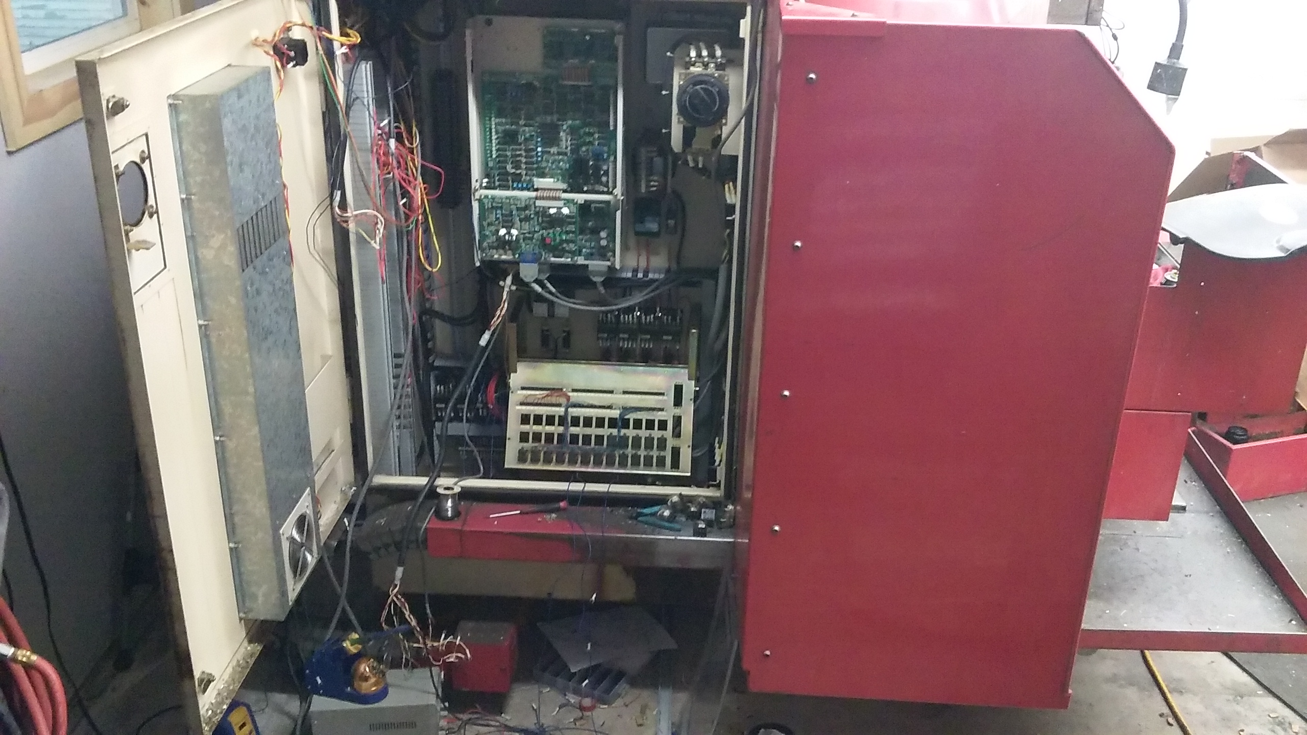
Working out all the relays and tool change I/o. Rewiring all the relays, contacts, and misc that needs handled for things to work. I hope to have this stuff hooked up to the 7i77 on Sunday and then start on the classic ladder for the ATC. Time to pick up and have a beer!
Please Log in or Create an account to join the conversation.
- tommylight
-

- Offline
- Moderator
-

9 years 8 months ago #87853
by tommylight
Replied by tommylight on topic 1982 Matsuura MC-500v Retrofit
Just so you know, i'watching you ! 
Dude, where's my beer?
Nice progress, for sure.
I finished mine a few days ago, in the mean time i did another retrofit on a plasma cutter, also finished today.
Regards,
Tom
Dude, where's my beer?
Nice progress, for sure.
I finished mine a few days ago, in the mean time i did another retrofit on a plasma cutter, also finished today.
Regards,
Tom
The following user(s) said Thank You: chopper79
Please Log in or Create an account to join the conversation.
9 years 8 months ago - 9 years 8 months ago #87858
by chopper79
Replied by chopper79 on topic 1982 Matsuura MC-500v Retrofit
Thank you
Sounds like me right now.... Trying to finish this thing up and multiple projects right now. I hope the classic ladder will be smooth sailing. Never worked with CL before so this will get interesting I am sure.
Sounds like me right now.... Trying to finish this thing up and multiple projects right now. I hope the classic ladder will be smooth sailing. Never worked with CL before so this will get interesting I am sure.
Last edit: 9 years 8 months ago by chopper79.
Please Log in or Create an account to join the conversation.
Time to create page: 0.112 seconds