dxf2gcode - plasma enhancements
- Joco
-
 Topic Author
- Offline
- Platinum Member
-

Less
More
- Posts: 532
- Thank you received: 327
12 May 2021 09:11 #208614
by Joco
dxf2gcode - plasma enhancements was created by Joco
In preparation for the eventual finishing of a cnc plasma build I have been looking at opensource tool chain options. Something along the lines of:
CAD (libreCAD or other tool able to create dxf or SVG files)
-->
Nesting (DeepNest)
-->
DXF to GCode( ??gcodegen??)
-->
linxcnc plasma controller (QTplasmac or similar)
I have been trying to solve for ??gcodegen??. Finding something that can create gcode that would be sensible for plasma use. By "sensible" I mean has the key elements of:
[1] baked in cutter compensation so it plays nice with plasmac and THC
[2] understands internal and external cuts and sets external CW and internal CCW to get the best from the CW swirl of the plasma plume
[3] has lead-ins and ideally lead-outs which can be adjusted to some degree including supressed if apprpriate
I'm sure there could be others to this list but that will do for a start. So after some hunting about and playing with the inkscape scripts, which is good but not quite what I wanted, I decided dxf2gcode was very close and just a little time investment could push it much closer from a plasma angle.
So after some time unpicking things I started adding some code to the fork of dxf2gcode on my github - dxf2gcode-plasma .
The branch being worked on is: github.com/joco-nz/dxf2gcode-plasma/tree/plasma-leadin
Ignoring the inevitable bugs I will be creating so early on I have the current functions generally working:
[1] baked cutter compensation supports lead ins
[2] contours on a dxf layer named PLASMA will have the cutting direction set to CW for outside and CCW for inside contours when autocuttercompensation setting is True.
There are some other changes I am working on and will post things as they progress.
I have made this visible to the dxf2gcode devs on their mail list and they can take/bake whatever they think worthy back into the official code line.
Hopefully might be of some use to some people.
Cheers - J.
CAD (libreCAD or other tool able to create dxf or SVG files)
-->
Nesting (DeepNest)
-->
DXF to GCode( ??gcodegen??)
-->
linxcnc plasma controller (QTplasmac or similar)
I have been trying to solve for ??gcodegen??. Finding something that can create gcode that would be sensible for plasma use. By "sensible" I mean has the key elements of:
[1] baked in cutter compensation so it plays nice with plasmac and THC
[2] understands internal and external cuts and sets external CW and internal CCW to get the best from the CW swirl of the plasma plume
[3] has lead-ins and ideally lead-outs which can be adjusted to some degree including supressed if apprpriate
I'm sure there could be others to this list but that will do for a start. So after some hunting about and playing with the inkscape scripts, which is good but not quite what I wanted, I decided dxf2gcode was very close and just a little time investment could push it much closer from a plasma angle.
So after some time unpicking things I started adding some code to the fork of dxf2gcode on my github - dxf2gcode-plasma .
The branch being worked on is: github.com/joco-nz/dxf2gcode-plasma/tree/plasma-leadin
Ignoring the inevitable bugs I will be creating so early on
I have the current functions generally working:[1] baked cutter compensation supports lead ins
[2] contours on a dxf layer named PLASMA will have the cutting direction set to CW for outside and CCW for inside contours when autocuttercompensation setting is True.
There are some other changes I am working on and will post things as they progress.
I have made this visible to the dxf2gcode devs on their mail list and they can take/bake whatever they think worthy back into the official code line.
Hopefully might be of some use to some people.
Cheers - J.
The following user(s) said Thank You: phillc54, tommylight, snowgoer540
Please Log in or Create an account to join the conversation.
- Joco
-
Topic Author
- Offline
- Platinum Member
-
Less
More
- Posts: 532
- Thank you received: 327
12 May 2021 10:40 - 12 May 2021 10:42 #208615
by Joco
Replied by Joco on topic dxf2gcode - plasma enhancements
Following same pattern as the MILL layer naming convention the following layer naming pattern will suppress lead-ins on a PLASMA layer.
PLASMA:1 Sl:1
: is the default separator used between the name/value pairs
The 1 after PLASMA can be any value.
The Sl is the Suppress layer indicator
1 = True
0 = False
This can be useful when you have a design in relatively thin metal and the pierce point is not distinguishable and having lead-ins adds no value. Or for a potion of the design they actually get in the way. Putting all those cuts on a single layer allows this to be dealt with on mass.
If other cuts will benefits from lead-ins then have them on another layer. For example
Layer 1 to suppress lead ins named: PLASMA:1 Sl:1
Layer 2 to be processed as a standard plasma layer named: PLASMA
Just remember that the code which automatically figures out what contours are inside others and therefore assigns the cut direction requires all those contours to be on the same layer. Equally if you have some contours that are causing issues with this then breaking them out to a different layer will solve that issue.
Also, while I remember it. Assuming you need to have unique layer names in your tool of choice then use the colon/number pattern to achieve this. i.e.
PLASMA:1
PLASMA:2
PLASMA:25
etc
Cheers - J.
Last edit: 12 May 2021 10:42 by Joco.
The following user(s) said Thank You: tommylight, snowgoer540
Please Log in or Create an account to join the conversation.
- andypugh
-

- Offline
- Moderator
-

Less
More
- Posts: 19875
- Thank you received: 4642
12 May 2021 21:35 #208656
by andypugh
Replied by andypugh on topic dxf2gcode - plasma enhancements
It's good to have free and open tools. But SheetCAM is very much an option here, surely?
Please Log in or Create an account to join the conversation.
- Joco
-
Topic Author
- Offline
- Platinum Member
-
Less
More
- Posts: 532
- Thank you received: 327
12 May 2021 22:45 #208670
by Joco
Replied by Joco on topic dxf2gcode - plasma enhancements
SheetCAM is 110 quid. About 214NZD excl taxes. It's not outrageous but its not free.
IF I start earning money from this plasma lark then SheetCAM would be the answer, no doubt about it. But for hobby/fun use while I'm just making low volume/one off stuff then I wanted to have an option I could pursue with just some of my time. Plus I have been enjoying the coding/understanding challenge. For me that's just all part of the hobby aspect. I enjoy the software/electronics challenge as much as the metal working challenge.
Cheers - J.
The following user(s) said Thank You: paulsao
Please Log in or Create an account to join the conversation.
- Joco
-
Topic Author
- Offline
- Platinum Member
-
Less
More
- Posts: 532
- Thank you received: 327
12 May 2021 22:50 #208671
by Joco
Replied by Joco on topic dxf2gcode - plasma enhancements
Proofed my workflow through to CAMotics. Base part done in libreCAD (a super simple part), the dxf pushed through DeepNest to get 30 parts on a sheet. Back into libreCAD to push the parts into a layer named PLASMA. Then into my version of dxf2gcode to create the kerf offset paths with lead-ins and export the gcode. Gcode run through CAMotics to proof behaviour.
Pretty happy so far. The attached image shows the end of the CAMotics simulation with all parts traced. You can just see the small lead-ins to the circles. Yo might need to make it reasonably large.
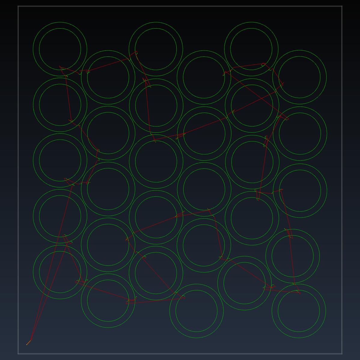
Pretty happy so far. The attached image shows the end of the CAMotics simulation with all parts traced. You can just see the small lead-ins to the circles. Yo might need to make it reasonably large.
Attachments:
The following user(s) said Thank You: snowgoer540
Please Log in or Create an account to join the conversation.
- Clive S
- Offline
- Platinum Member
-
Less
More
- Posts: 2204
- Thank you received: 486
12 May 2021 23:58 #208675
by Clive S
Sheetcam is free for a few lines of code so it is possible to spit the cuts up into sections then glue it together to make the gcode
Replied by Clive S on topic dxf2gcode - plasma enhancements
Proofed my workflow through to CAMotics. Base part done in libreCAD (a super simple part), the dxf pushed through DeepNest to get 30 parts on a sheet. Back into libreCAD to push the parts into a layer named PLASMA. Then into my version of dxf2gcode to create the kerf offset paths with lead-ins and export the gcode. Gcode run through CAMotics to proof behaviour.
Pretty happy so far. The attached image shows the end of the CAMotics simulation with all parts traced. You can just see the small lead-ins to the circles. Yo might need to make it reasonably large.
Sheetcam is free for a few lines of code so it is possible to spit the cuts up into sections then glue it together to make the gcode
Please Log in or Create an account to join the conversation.
- Joco
-
Topic Author
- Offline
- Platinum Member
-
Less
More
- Posts: 532
- Thank you received: 327
13 May 2021 00:12 #208677
by Joco
Replied by Joco on topic dxf2gcode - plasma enhancements
lol - are you guys on commission? 
180 is what I believe the line limit is. But I'm having fun with my tinkerings.
180 is what I believe the line limit is. But I'm having fun with my tinkerings.
The following user(s) said Thank You: phillc54
Please Log in or Create an account to join the conversation.
- snowgoer540
-

- Offline
- Moderator
-
Less
More
- Posts: 2553
- Thank you received: 887
13 May 2021 01:36 #208683
by snowgoer540
Replied by snowgoer540 on topic dxf2gcode - plasma enhancements
I think it’s a worthwhile endeavor. I actually had it on the “maybe during the winter” to look at list. I’ve mentioned before that I think it would make a good addition to the current conversational offerings. I could see it coming in handy from time to time. I enjoy tinkering in the code myself, I agree it’s part of the hobby to me.
Keep up the good work!
Keep up the good work!
Please Log in or Create an account to join the conversation.
- Joco
-
Topic Author
- Offline
- Platinum Member
-
Less
More
- Posts: 532
- Thank you received: 327
13 May 2021 02:27 #208685
by Joco
Replied by Joco on topic dxf2gcode - plasma enhancements
I think I might have a basic working model for lead-outs. Attached pic shows post simulation state of a shape with lead-in/outs on an outside and inside cut. All very simple at the moment. Next need to try and take some of the magic out of what is happening as well as allow independent suppression of lead-ins and lead-outs. I might do this via a layer naming setting.
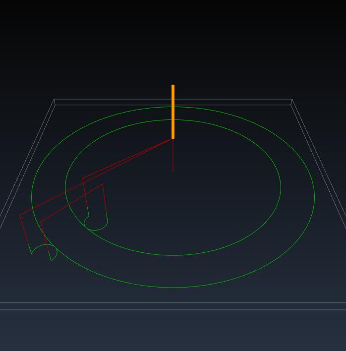
Cheers - J.
Cheers - J.
Attachments:
Please Log in or Create an account to join the conversation.
- tommylight
-

- Away
- Moderator
-
Less
More
- Posts: 21712
- Thank you received: 7418
13 May 2021 10:05 #208719
by tommylight
Replied by tommylight on topic dxf2gcode - plasma enhancements
Nice work, thank you.
Personally, i would skip everything regarding lead outs, it is pretty much useless for plasma cutting and causes a lot of issues when cutting small parts.
Personally, i would skip everything regarding lead outs, it is pretty much useless for plasma cutting and causes a lot of issues when cutting small parts.
Please Log in or Create an account to join the conversation.
Time to create page: 0.430 seconds