Dell Optiplex 745, test axis fails!
- lledee
- Offline
- New Member
-

- Posts: 15
- Thank you received: 0
I'm conpletely new to this whole thing, CNC and especially Linux. I have a kit ordered from Probotix with the RF Isolated Parallel breakout board and the Uni-polar Stepper driver.
I've tried many times to get the computer to spin a motor but every attempt has failed.
I'm using a Dell Optiplex 745 and in the settings for the parallel port in the BIOS menu I'm not exactly sure what to choose since i don't have the option for EPP. Is this a must have for the bi-directional communications to work on this controller or is it simply for feedback and i can get by without using the EPP setting?
I've tried going with some default settings and clicking test axig when going through stepconfiguration but I've never seen any movement. I'm thinking it may be something to do with the wiring of the controller and driver but i'm not sure. I've read over the wiring configuration many times and think i'm doing the right thing...
Thanks,
Louis'
Please Log in or Create an account to join the conversation.
- DaBit
- Offline
- Platinum Member
-

- Posts: 446
- Thank you received: 35
- Have you tried the regular LPT addresses in Stepconf? 0x378, 0x278, 0x3BC?
- Do you power both sides of you BOB? PC side and driver side?
- Pinning is correctly entered in stepconf? Should be:
PIN Signal
1 A Enable
2 X Step
3 X Direction
4 Y Step
5 Y Direction
6 Z Step
7 Z Direction
8 A Step
9 A Direction
10 E-stop
11 Z Limit
12 Y Limit
13 X Limit
14 X Enable
15 Aux Input
16 Y Enable
17 Z Enable
- Did you invert the step lines?
Please Log in or Create an account to join the conversation.
- lledee
- Offline
- New Member
-
- Posts: 15
- Thank you received: 0
- I do remember seeing 0x378 as the address, i didn't see anything else in the dropdown.
-I am powering the PC side of the breakout using USB and the Driver side using the supply for the drivers as well( the drivers and the driver side of the breakout have the same power supply).
-I'm at work at the moment so i will double check the pinning when i get home but i'm quite positive that i had everything set according to the documentation like below:
PIN Signal
1 A Enable
2 X Step
3 X Direction
4 Y Step
5 Y Direction
6 Z Step
7 Z Direction
8 A Step
9 A Direction
10 E-stop
11 Z Limit
12 Y Limit
13 X Limit
14 X Enable
15 Aux Input
16 Y Enable
17 Z Enable
This looks to be exactly what you pasted here!
I haven't inverted anyanything... Is this only for the direction the motor spins or for receiving signals from the computer? Should these lines be inverted?
Thanks for the help as i was quite nervous to post, i'm not a person who likes to post but i do like to read... I'm working on that!
Please Log in or Create an account to join the conversation.
- DaBit
- Offline
- Platinum Member
-
- Posts: 446
- Thank you received: 35
Thanks for that super fast reply.
- I do remember seeing 0x378 as the address, i didn't see anything else in the dropdown.
You can enter any address you want, zo you might want to try 0x278 and 0x3BC also.
(to start with..)
-I am powering the PC side of the breakout using USB and the Driver side using the supply for the drivers as well( the drivers and the driver side of the breakout have the same power supply).
Should be OK I suppose.
to the documentation like below:
..
This looks to be exactly what you pasted here!
I copied it from the PDF at the probotix site too

I haven't inverted anyanything... Is this only for the direction the motor spins or for receiving signals from the computer? Should these lines be inverted?
This document says 'The ProboStep is negative logic. The STEP lines should be inverted in your
software.'
It also says:
'Minimum pulse width for the step pulse is 5 uS'.
Make sure you set that too (5us = 5000ns)
Also, do you need/have a 'logic supply regulator' on those drives? I don;t think so, but I am not familiar with the Probotix products.
Please Log in or Create an account to join the conversation.
- lledee
- Offline
- New Member
-
- Posts: 15
- Thank you received: 0
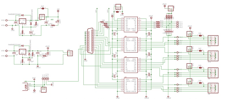
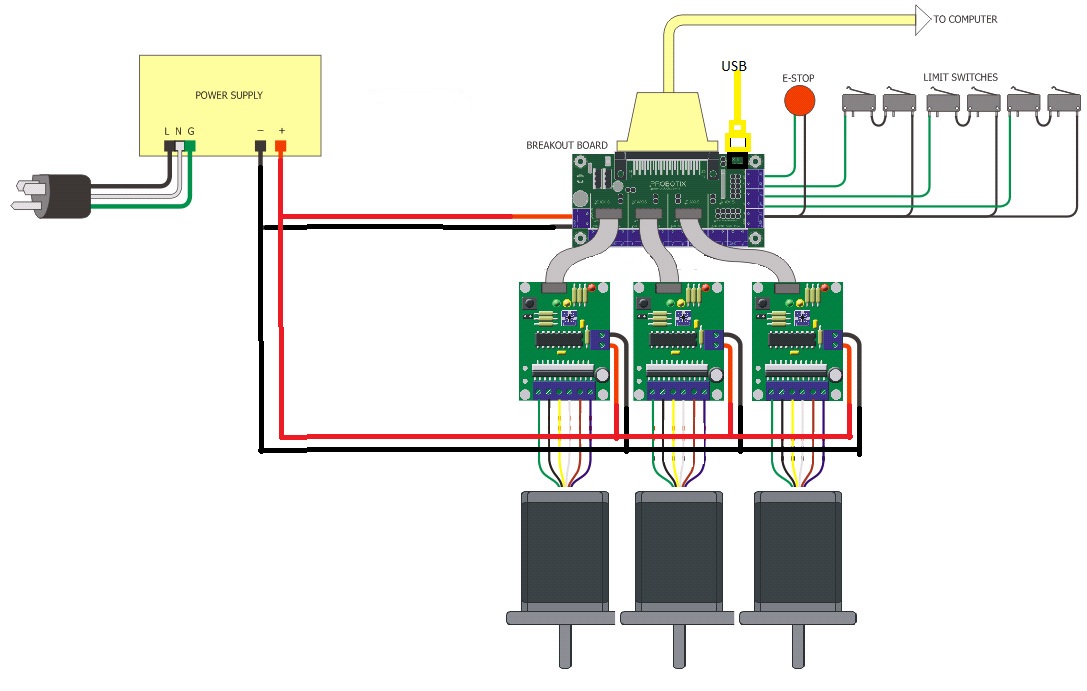
From what I've read and if you look at the schematics you can apply power to the individual drivers from the breakout.
I've wired everything as shown in the picture attached. the only difference is i don't have any of the interrupts hooked up and i don't have the ground block.

From what I can tell there is two supplys powering the breakout, the pc side and the driver side. The driver side has a regulator that shares power via a jumper for each axis through the jumper cables to each axis. This is what I've done and the lights come on for each Axis. I think you hit the spot with the inverted signals...
FYI on the each driver board there is a spot that a regulator can provide logic power but there is no regulator soldered onto them, and i don't think it's so necessary also.
So for future reference, will the limit switches and the e-stop button work with the SPP Settings?
Please Log in or Create an account to join the conversation.
- DaBit
- Offline
- Platinum Member
-
- Posts: 446
- Thank you received: 35
How did you reply like that? breaking down my response into sections...
Using multiple [ quote ] and [ /quote ] sections in the reply.
and i don't have the ground block.
I suppose you did connect all the GND wires in a star?
(since you seem to be able to read schematics, I think you did)
I think you hit the spot with the inverted signals...
I am not sure. Normally the motors should also move with the step inverted.
and i don't think it's so necessary also.
Neither do I.
So for future reference, will the limit switches and the e-stop button work with the SPP Settings?
Yes, they will. A SPP port provides 5 inputs.
If you are a little confident with electronics: what happens if you pulse the steppers manually by touching a jumper wire between the appropriate step-pin on the LPT and the +5V or GND coming from the USB?
Please Log in or Create an account to join the conversation.
- lledee
- Offline
- New Member
-
- Posts: 15
- Thank you received: 0
I suppose you did connect all the GND wires in a star?
(since you seem to be able to read schematics, I think you did)
I just paralleled everything coming from the supply!
I am not sure. Normally the motors should also move with the step inverted.
Everything is working now!
So for future reference, will the limit switches and the e-stop button work with the SPP Settings?
Yes, they will. A SPP port provides 5 inputs.
I've found the setting for EPP, which I've overlooked!
If you are a little confident with electronics: what happens if you pulse the steppers manually by touching a jumper wire between the appropriate step-pin on the LPT and the +5V or GND coming from the USB?
I've quite comfortable with electronics, I have an Industrial Electronics degree (associates of course) and i have 7 years job experience. I can read schematics and all that good stuff.
I've finally gotten everything working by just that port setting in the BIOS i think. I also found this link that they had the same problems, go figure...
I really appreciate the help, now it's time to dig in and get all of the correct settings in place, the fun stuff! I wish there were some sort of button to click and buy a beer, or cigar, or whatever it is you do
")
Louis'
Please Log in or Create an account to join the conversation.
- DaBit
- Offline
- Platinum Member
-
- Posts: 446
- Thank you received: 35
Whether you set the port in the BIOS to SPP, EPP or ECP should not matter. EPP/ECP has extra capabilities, but it is still backwards compatible. If the software doesn't use the extra functionality (data transport basically, getting blocks of bytes from A to
") it should not make a difference.
it should not make a difference.But on the other hand: not much is 'standard' in the PC world. If something is 'standard' you can translate that into 'it usually works'.
Regarding the thank you: normally it is andypugh answering all my questions, I thought I would do something back
")
But nice to hear that it works now. Happy CNC-ing!
Please Log in or Create an account to join the conversation.
- lledee
- Offline
- New Member
-
- Posts: 15
- Thank you received: 0
As long as 'parallelled' means that you run separate wires to the power supply (for both power and ground) instead of a daisy-chain, its OK. Don't do the power supply -> drive #1 - drive #2 -> drive #3 routing of the cabling.
You are correct, all of the wires will be separate runs from the power supply itself.
Regarding the thank you: normally it is andypugh answering all my questions, I thought I would do something back
But nice to hear that it works now. Happy CNC-ing!
Well if it wasn't for Andy then you probably wouldn't have helped so i really appreciate it once again. I'll make some more detailed documentation about the wiring and pictures of my Shapeoko 2 once im done. Pulleys are in the mail and should be at my house today, these should be the last things i'm waiting on to get up and running again, I've just upgraded the motors from NEMA 17 to NEMA 23, along with a few other upgrades. I'd just looking for PCB's mainly in the end.
I put together a google site, it's definitely WIP but you can check it out if you'd like, it should be access to public...Here is the link .
I only started on it a few weeks ago while waiting on parts and at a stand still.
Please Log in or Create an account to join the conversation.
- lledee
- Offline
- New Member
-
- Posts: 15
- Thank you received: 0

Please Log in or Create an account to join the conversation.