Dell Optiplex 745, test axis fails!
- lledee
- Offline
- New Member
-

- Posts: 15
- Thank you received: 0
First... Silly me I only changed the microsteooing on one driver. I trusted your settings and knew that they were right but something I was doing was wrong.
Secondly... My previous calculations weren't the pitch times the teeth. It was simply the pitch times the belts teeth per inch. Both silly mistakes but now at least I understand!! One inch is actually one inch now
")
Please Log in or Create an account to join the conversation.
- lledee
- Offline
- New Member
-
- Posts: 15
- Thank you received: 0
Anyway, i thought i'd let you in on what I've done.
Please Log in or Create an account to join the conversation.
- DaBit
- Offline
- Platinum Member
-

- Posts: 446
- Thank you received: 35

One tip: try to only mill the copper and hit as little glass fiber as possible. The glass dulls the endmills and engraving bits quickly.
Current status of my mill-to-be:
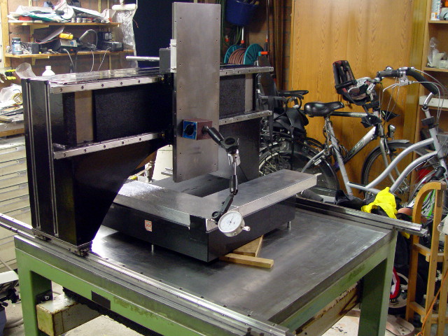
Gantry is loose on the carriages, currently trying to square X,Y and Z. I'm going for better than 0,01mm/100mm, so that probably means another several hours of fun with the dial indicator.
Please Log in or Create an account to join the conversation.
- BigJohnT
-

- Offline
- Administrator
-

- Posts: 6999
- Thank you received: 1176
JT
Please Log in or Create an account to join the conversation.
- lledee
- Offline
- New Member
-
- Posts: 15
- Thank you received: 0
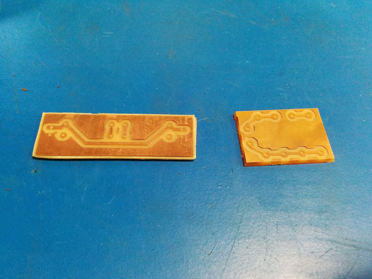
Looking good! I like the clean edges. This was my first PCB-milling attempt :
You've got some very fine vias in there! What program are you using? I've been using EagleCAD with the PCB2Gcode pluglin but my shapes don't look like yours one bit! What's this board of yours for? looks like some higher voltages, what's the max voltage and current you've been running through these boards? also temp you've seen it withstand...
One tip: try to only mill the copper and hit as little glass fiber as possible. The glass dulls the endmills and engraving bits quickly.
Agreed, and I've read many many many posts about this, this is the reason i'd like to have a cheap height probe to map the heights of the PCB before milling. I'd like to have a simple conductive probe and only use it for when doing PCB's for now. Later if i really feel like it and actually know how to use everything i have so far i'll get the nice probes or build one by then.
BigJohnT, anything you've seen or done with this in mind, or seen?
Gantry is loose on the carriages, currently trying to square X,Y and Z....
I haven't done much checking around on this but do you have any links you would like to share about squaring up each axis? I'd really appreciate it.
I also need to replace the sacrificial board that came with original Shapeoko 2 kit. It's cut into two pieces and i really don't like how it sags in the middle and has two different heights etc. Do you guys have any suggestions on materials or things i could implement when doing this? Keep in mind i am a hobbyist just as well as the next guy
")
Please Log in or Create an account to join the conversation.
- DaBit
- Offline
- Platinum Member
-
- Posts: 446
- Thank you received: 35
Schematic
Board
And indeed, it uses 350VDC at 5Amps to control a Kress FME1050-1 router spindle.
For processing it to G-code I used CamBam. I was not very satisfied with the Eagle pcbgcode plugin. The separate 'PCB2Gcode' Linux program is a bit better, but it still doesn't match CamBam's flexibility. CamBam also allows me to draw in the extra isolation distances needed, for example.
I like CamBam; it's a lower-end CAM program but so far it handles all 3-axis milling work well and it is affordable.
Regarding squaring up: it really depends on what you have access to. I have a small class 00 surface plate and two very accurately hand-scraped blocks, so in my case I put the two blocks in an L-shape, rock the gantry forward and backwards and position the block until the dial indicator needle does not move anymore (then one side of the block is parallel to Y-axis motion), and do the same by rocking the Z-axis plate left and right until the needle does not move. Then X and Y are square.
Sounds simple, and it is. But in reality it takes a couple of hours to reach that point (I am not there yet, far from it even).
X-axis parallel to table: put the indicator on the surface plate, rock Z-axis plate left/right, adjust setscrews and tension screws until it does not move. This is not that important since I need the mill to flatten it's own table. But the less material I have to remove, the better.
Z-axis perpendicular to XY plane: put one of the blocks on the surface plate, move Z-axis up and down until the needle stays still. And then X-axis parallel to table is probably off.
When done, leave it for a week so things can settle, and then start over since it did certainly move a bit here and there.
If you are not looking for the last thou, I would suggest that you put 2 slabs of material om top of each other, mill a square through both at the same time, and flip one over on the other. If everything is square it is always a perfect match no matter how you position the squares relative to each other. If not everything is square, correct it mechanically, or use the millkins with skew correction.
Please Log in or Create an account to join the conversation.
- lledee
- Offline
- New Member
-
- Posts: 15
- Thank you received: 0
I just started using pycam for cam. I want to try CamBam though, seems like the possibilities are endless from the way everyone is talking about it.
millkins, is this something you add the offset in the plugin or whatever it is then LinuxCNC will apply the corrections in the software?
That was a quick response!
I like the board and i wanted something like it but simpler... Who knows maybe one day i will get around to this one or something similiar!
Please Log in or Create an account to join the conversation.
- DaBit
- Offline
- Platinum Member
-
- Posts: 446
- Thank you received: 35
Trace is what i meant by "via". I agree about the SMD and also its space saving!
Some traces turned out a little too thin due to burying the V-cutter a bit too deep in the PCB. As I said: it was my first.
I just started using pycam for cam. I want to try CamBam though, seems like the possibilities are endless from the way everyone is talking about it.
I can't help it, but I just like it. It is fairly spartan, but you can do some weird things with it such as importing an existing G-code file, extract shapes from it, and generate new code for a different sized mill for example.
I did try PyCAM also, and it does the job. But often I only want to mill a small part of the job using parallel/scanline 3D toolpaths and use regular 2,5D toolpaths for pockets, holes, etc. CamBam is more flexible in that area.
millkins, is this something you add the offset in the plugin or whatever it is then LinuxCNC will apply the corrections in the software?
It replaces the trivkins module. and allows you to correct a skew between X and Y.
I did not use it yet, but I looked very closely at the code in case my mill turns out a little less perfectly square and straight than intended. After all I am doing most of the construction using a cordless drill and a screwdriver. Not much hightech equipment is used for that.
It would be fairly easy (for me, that is) to derive a DaBit-kins module from millkins that corrects the mechanical errors. If they are actually correctable, of course.
I like the board and i wanted something like it but simpler... Who knows maybe one day i will get around to this one or something similiar!
I still have to put some effort in the software. The problem with 'routers' is their low inertia and the tendency to drop RPM when load is increased. That is a feature of the universal AC motor.
I wanted it to react quickly enough to keep RPM constant when going from air to aluminium, which is also why I feed the motor DC. AC would limit me to 100Hz which is too slow anyway (these motors are QUICK).
But this turns out to be pretty hard. Current software does no better than the speed control already available on the Kress FME1050 (which is also closed-loop using a tacho).
An inner control loop that adjustst motor voltage based on current and an outer loop controlling RPM based on incoming PWM (which is measured digitally) seems the ticket to success, but I upgraded to one of those Chinese 3kW 24000rpm spindels quite some time ago and that is a much better spindle than a router will ever be.
Please Log in or Create an account to join the conversation.