joint 0 on limit switch error
- andypugh
-

- Offline
- Moderator
-

- Posts: 19863
- Thank you received: 4636
If you look in your HAL file there is a line "setp pwmgen.0.frequency 5". Just change that.Where do I change the frequency value from 5 Hz to 25 Hz? By the way, what does the frequency do?
Without knowing the parameters of your VFD I can't even guess. Is it 3-phase or single phase? What current? Just choose the cheapest that has the right current rating and number of phases.I searched eBay and found too many Rasmi devices. Perhaps you could kindly quote a model number for me?
Please Log in or Create an account to join the conversation.
- fc60
- Offline
- Premium Member
-

- Posts: 124
- Thank you received: 9
My latest effort...
I wired the VFD power direct to the socket in the wall bypassing the CNC control box.
I connected the signal wires to the VFD. FWD, REV, VC, GND.
Start the machine, HOME all axis, press "F2" and machine power up.
Issued S1000M03 and machine shuts off after spindle moved slightly. "joint 0 on limit switch error"
I am able to press "F2" and restart machine power.
Next, I disconnect all signal wires to the VFD leaving only power connected bypassing CNC box.
Adjusted VFD to run manually.
Plugged VFD into the wall socket and it runs fine without any power to the CNC machine.
Powered up CNC machine, HOME all axis, walk behind machine and manually start spindle.
Spindle runs fine; but, I get the "joint 0 on limit switch error" and machine shuts off.
With the spindle running, I am able to restart the machine via the "F2" key; but, it only runs for about 5-10 seconds then "joint 0 on limit switch error"
Manually turn off spindle and I am able to restart machine again.
Cheers,
Dave
Please Log in or Create an account to join the conversation.
- andypugh
-
- Offline
- Moderator
-
- Posts: 19863
- Thank you received: 4636
Are your limit switches of the type that light up when activated? Can you see them actuating? If you can then it might not be noise in the wires. Perhaps the electric motor is actually "leaky" and is directly interfering with the proximity switches.
Connecting the VFD to a separate wall socket won't necessarily help. Without an input filter on the mains supply to the VFD the high-frequency noise propagates through the whole wiring system.
I would be tempted to see what the limit switches do if arranged to be "looking" at targets that are electrically isolated from the machine frame (purely as an experiment).
You can just disconnect the limit switch inputs (in HAL) and then you will be able to watch the home-switch value with Halscope to see what is going on and whether the input is noisy or solidly set.
Please Log in or Create an account to join the conversation.
- fc60
- Offline
- Premium Member
-
- Posts: 124
- Thank you received: 9
Yes.
Are your limit switches of the type that light up when activated?
Yes, a small LED on the bottom. Y axis is exposed. X and Z are inside shielded flex cable. I next plan to remove the flex cable on X and Z to look for damage.
I would be tempted to see what the limit switches do if arranged to be "looking" at targets that are electrically isolated from the machine frame (purely as an experiment).
How do I accomplish this? Place a metal washer on top of the sensor?
You can just disconnect the limit switch inputs (in HAL) and then you will be able to watch the home-switch value with Halscope to see what is going on and whether the input is noisy or solidly set.
I will need some help on this. If I disable the limit switch inputs in HAL will I still be able to HOME the machine?
Please Log in or Create an account to join the conversation.
- andypugh
-
- Offline
- Moderator
-
- Posts: 19863
- Thank you received: 4636
I will need some help on this. If I disable the limit switch inputs in HAL will I still be able to HOME the machine?
Yes. You can leave the axis.N.home-sw-in HAL pin connected, but remove the pos-lim-sw and neg-lim-sw connections.
I am not sure what your HAL file looks like at the moment, but you can just comment-out the line that looks like
net limit match8.0.out axis.0.neg-lim-sw-in# net limit match8.0.out axis.0.neg-lim-sw-inNote that you only seem to have one limit switch input, so don't read too much into what the error message says when the limit trips.
Please Log in or Create an account to join the conversation.
- fc60
- Offline
- Premium Member
-
- Posts: 124
- Thank you received: 9
Your suggestion of commenting out the # net limit match8.0.out axis.0.neg-lim-sw-in works well. The machine boots up, HOME's, and I can successfully run a program with M03 commands.
Does the above mean I possibly have defective Inductive-Sensors? You mentioned using HAL Scope to observe the limit switch circuit. I know where to find HAL Scope; but, that is where the journey ends. Which of the many parameters should I be watching and under what conditions?
I have a new sensor in the mail and should arrive soon. I have already replaced one sensor that was physically damaged and before I disassemble the remaining two it would be nice to see if I can determine which one is faulty, if possible. However, I have no qualms about replacing them both.
I did as you suggested and contacted Ramsi in England. They replied with their recommendation for a filter. Would the filter be installed in the CNC control box or in the small electrical box on the machine that houses the VFD control?
I cannot thank you and the other on the Forum for your help. I would never have gotten this far without your support. MANY THANKS!!!
Please Log in or Create an account to join the conversation.
- andypugh
-
- Offline
- Moderator
-
- Posts: 19863
- Thank you received: 4636
The only problem with this is that you are depending on the soft-limits to keep things in range. But they are quite dependable unless you have a stepper slip.Your suggestion of commenting out the # net limit match8.0.out axis.0.neg-lim-sw-in works well. The machine boots up, HOME's, and I can successfully run a program with M03 commands.
It is possible that the sensors are faulty, or it could be something strange about their power supply when the spindle is running, or possibly even magnetic effects through the machine base. In your case I would Halscope the parallel port pin that the limits are connected to.Does the above mean I possibly have defective Inductive-Sensors? You mentioned using HAL Scope to observe the limit switch circuit. I know where to find HAL Scope; but, that is where the journey ends. Which of the many parameters should I be watching and under what conditions?
I have a new sensor in the mail and should arrive soon. I have already replaced one sensor that was physically damaged and before I disassemble the remaining two it would be nice to see if I can determine which one is faulty
Try running with only one connected at a time, when running the VFD and monitoring the pin with Halscope.
It goes as close as possible to the VFD.Would the filter be installed in the CNC control box or in the small electrical box on the machine that houses the VFD control?
Please Log in or Create an account to join the conversation.
- fc60
- Offline
- Premium Member
-
- Posts: 124
- Thank you received: 9
"Try running with only one connected at a time, when running the VFD and monitoring the pin with Halscope."
Some clarification for the above. The sensors have three wires. Two appear to supply voltage to the sensor and the third is used as a "trip". The power wires are all soldered together. The "trip" wires have spade lugs and are easily disconnected.
When you say "one connected at a time" does that mean all the wires; or, just the "trip" wire?
According to the BOB documentation, "pin 12 > limit switches status to PC".
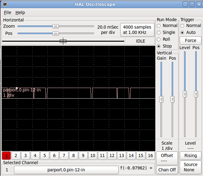
HalScope offers two pin 12 choices. parport.0.pin-12.in and parport.0.pin-12.in-not. I selected the former and an image of the result is attached.
Cheers,
Dave
Please Log in or Create an account to join the conversation.
- andypugh
-
- Offline
- Moderator
-
- Posts: 19863
- Thank you received: 4636
Some clarification for the above. The sensors have three wires. Two appear to supply voltage to the sensor and the third is used as a "trip". The power wires are all soldered together. The "trip" wires have spade lugs and are easily disconnected.
When you say "one connected at a time" does that mean all the wires; or, just the "trip" wire?[\quote]
Yes, you can leave them all powered.
Do you know if the sensors are NPN or PNP? I seem to recall that one variant is better-suited to use with 5V logic than the other.
If you look at this page: sensortech.wordpress.com/2011/01/18/indu...e-basics-npn-vs-pnp/
You can see that PNP switches the sense line to GND and the other switches it to +Supply. As most proximity switches don't work below 8V (I have some that say 8 - 30V and some are 10 - 30V) switching the BoB inputs to +12V or + 24V might not be what you want to do.
In any case you want to look at the opto-coupler in the BoB input as the "load" in those diagrams, and try to think in terms of current flow through that opto-coupler rather than voltage to the pin.
HalScope offers two pin 12 choices. parport.0.pin-12.in and parport.0.pin-12.in-not. I selected the former and an image of the result is attached.
The Halscope shows the output permanently high with noise spikes pulling it low. This isn't what I had expected to see as your limit switches seem to be connected to the same parport.0.pin-12-in.
What does the trace look like with the VFD turned off? If it is permanently low then I am very puzzled about what is going on.
Please Log in or Create an account to join the conversation.
- daxur666
- Offline
- New Member
-

- Posts: 17
- Thank you received: 0
Please Log in or Create an account to join the conversation.