Mesa 7i77 output voltages
- jwsigler
- Offline
- Senior Member
-

Less
More
- Posts: 63
- Thank you received: 1
11 Aug 2016 23:16 #78654
by jwsigler
Mesa 7i77 output voltages was created by jwsigler
I am trying to set up my HAL files and I am getting some inconsistent results. I was able to get Linuxcnc to load, I could even jog the table a little before getting a following error, and I was able to get some of my control buttons to operate the relays in my machine.
The problem I have is that some the the output channel are suppose to operate indicator lights and that is not happening.
To trouble shoot the problem, I edited my custom postgui hal file to include the following commands:
net test-00 hm2_5i25.0.7i77.0.0.output-00
sets test-00 true
net test-01 hm2_5i25.0.7i77.0.0.output-01
sets test-01 true
net test-02 hm2_5i25.0.7i77.0.0.output-02
sets test-02 true
and so forth up to output-15
As far as I know, run linuxcnc with this hal should turn on all the output channels on the 7i77 board.
My power supply is delivering 23.8 VDC and the power on TB2 is as follows:
pin 1 23.8 vDC
pin 2 0.0 vDC
pin 3 23.8 vDC
pin 4 23.8 vDC
pin 5 23.8 vDC
pin 6 0.0 vDC
pin 7 0.0 vDC
pin 8 0.0 vDC
When I run linuxcnc and check the outputs on terminal TB7 adn TB8, I get the follwoing:
output-00 15.5 Vdc output-08 14.2 Vdc
output-01 23.8 Vdc output-09 23.8 Vdc
output-02 23.8 Vdc output-10 23.8 Vdc
output-03 0.7 Vdc output-11 0.7 Vdc
output-04 23.8 Vdc output-12 23.8 Vdc
output-05 23.8 Vdc output-13 23.8 Vdc
output-06 23.8 Vdc output-14 23.8 Vdc
output-07 0.7 Vdc output-15 0.8 Vdc
Like I said, I would have expected everything to be at 23.8 when I set all the outputs to true, and it seems strange that I get a similar pattern on both TB7 and TB8. Do I have the 7i77 in some strange mode? I have include the basic hal file created be pncconf if that helps.
Does anyone know why I am not getting all outputs at max voltage?
Thanks
Please Log in or Create an account to join the conversation.
- PCW
-

- Offline
- Moderator
-

Less
More
- Posts: 17961
- Thank you received: 5265
12 Aug 2016 02:18 #78658
by PCW
Replied by PCW on topic Mesa 7i77 output voltages
This is at least part of the issue (from your hal file):
net spindle-on hm2_5i25.0.7i77.0.0.output-00
# --- MACHINE-IS-ENABLED ---
net machine-is-enabled hm2_5i25.0.7i77.0.0.output-03
If you want to test outputs make sure you dont have dueling sources
net spindle-on hm2_5i25.0.7i77.0.0.output-00
# --- MACHINE-IS-ENABLED ---
net machine-is-enabled hm2_5i25.0.7i77.0.0.output-03
If you want to test outputs make sure you dont have dueling sources
Please Log in or Create an account to join the conversation.
- jwsigler
- Offline
- Senior Member
-
Less
More
- Posts: 63
- Thank you received: 1
12 Aug 2016 04:55 #78662
by jwsigler
Replied by jwsigler on topic Mesa 7i77 output voltages
I went back out and rechecked the outputs. I actually had commented those lines out in order to get linuxcnc to run. When I just rechecked the outputs, outputs 00 thru 07 were still the same, but outputs 08 thru 15 now measuered as
Output-08 1.1
Output-09 2.8
Output-10 3.0
Output-11 1.1
Output-12 3.8
Output-13 3.0
Output-14 3.1
Output-15 3.1
If I modified the custom hal file and turned off outputs 00 through 07, outputs 08 through 15 remeasured as the original 14 / 23.8 / 23.8 / 0.7 / 23.8 / 23.8 / 23.8 / 0.7 values.
I also unplugged the caps on all the headers, except TB2, to insure that nothing could be conflicting, but this did not make any difference. With no wires connected, I am not drawing any amperage at all so I do not think it could be an issue with available power.
Are there any mode setting that could be causing this?
Please Log in or Create an account to join the conversation.
- PCW
-
- Offline
- Moderator
-
Less
More
- Posts: 17961
- Thank you received: 5265
12 Aug 2016 12:51 #78668
by PCW
Replied by PCW on topic Mesa 7i77 output voltages
First: the output voltages have significant leakage so cannot be measured with a 10 megohm input voltmeter
second, to make sure you have no mistakes or conflicts, set outputs with setp, _NOT_ sets
A better way to measure outputs is to loop them back to 7I77 field inputs (you can measure them when they have a the input load)
second, to make sure you have no mistakes or conflicts, set outputs with setp, _NOT_ sets
A better way to measure outputs is to loop them back to 7I77 field inputs (you can measure them when they have a the input load)
Please Log in or Create an account to join the conversation.
- jwsigler
- Offline
- Senior Member
-
Less
More
- Posts: 63
- Thank you received: 1
12 Aug 2016 16:14 #78674
by jwsigler
Replied by jwsigler on topic Mesa 7i77 output voltages
Thanks for the guidance. I can easily edit the HAL file and change the sets commands to setp. As far as your comment about looping back, what you are suggesting is that I run a wire from each output terminal to one of the input terminals, but once I run the program and turn the outputs on, am I to measure the voltage using the input terminal, or still measure the voltage with a volt meter? I believe there are a couple of inputs that can be switched through some mode setting to measure actual input voltage, but aren't most of the input terminals going to simple give me a true or false reading? If the output terminal provides 15 volts like some of my measurements suggest, that would turn an input from false to true, but it would not be sufficient to light up my 24 vdc indicator leds which is what I want these outputs to do.
As far as how I measure the voltage on the output terminals, how do you suggest I measure it? The reason I started in on this investigation was because the 7i77 was not turning on simple led indicator lamps when I did a simple exercise and told it to turn on all the outputs that were connected to the indicator lamps. So initially I did a sudo type of measuring by simply asking the outputs to light up 24 volt leds.
When I first started in on setting up the hal commands, my first Hal command was to get the computer to turn on the 24VDC main power relay. I installed a main power relay that controlled all 24VDC power, other than the power going to the 7i77 board. I did not want 24VDC power going anywhere else until Linuxcnc was actually up and running just in case some problem or error would occur. In my custom hal file, I have two commands (which are now commented out) that do an unconditionally turn on of this relay. That hal command worked right off the bat.
Next I programmed in the hal command to control my reset button which would start up the legacy drive enable relay circuit that enables all the axis drives. This circuit always goes through all the limit switches, spindle motor overload switch, and several other analog error checks so that the relay circuit shuts down if any major error occurs. This was the same hardware circuit that the previous Dynapath controller used and it seems a good solid approach for safety. It took a couple of tries to get these hal commands figured out, but I finally got it running.
After that I actually got the table to jog a little in each direction, but got a following error. Instead of solving the following error, I decided to make sure that all of my other simpler devices were working which is when I inputted hal commands to turn on my indicator lamps and found only one of the lamps would lite. It was at that time I started trying to turn on all the output terminals to see what voltages I was getting.
Does it sound like I have anything wired wrong? It seems strange that if my voltmeter is not capable of measuring the voltage, because it measure the full system voltage of 23.8 Vdc on some of the terminal and not on the others? Can you tell me how I should measure the voltage on the outputs if my voltmeter will not work, or tell me what type of voltmeter I need to measure the outputs? I also do have some separate 24 vdc indicator lamps that I wired up to long leads and which I had clipped onto various terminals when I had the old Dyanpath controller still in the machine and I was trying to map out the legacy circuit. I could hook those indicator lamps up to the output terminals if that would be a better approach?
Thank for your assistance.
Please Log in or Create an account to join the conversation.
- PCW
-
- Offline
- Moderator
-
Less
More
- Posts: 17961
- Thank you received: 5265
12 Aug 2016 16:24 #78675
by PCW
Replied by PCW on topic Mesa 7i77 output voltages
What I am saying is that you cannot use a 10 Meg ohm input impedance voltmeter to measure sourcing voltage switches
(even 1 uA of leakage current will show up as 10V) If you wire an output to a field input (~22K load) that same 1 uA leakage would only result in a 22 mV reading. In other words you need a load (and a input pin will do)
Also be careful and follow the 7I77 manual when driving a large relay (anything more than 60 mA needs a flyback diode)
Please Log in or Create an account to join the conversation.
- jwsigler
- Offline
- Senior Member
-
Less
More
- Posts: 63
- Thank you received: 1
12 Aug 2016 19:02 #78686
by jwsigler
Replied by jwsigler on topic Mesa 7i77 output voltages
Thanks for your response.
Sorry if I do not fully understand all of your explanations. This level of electronics is a little out of my area of expertise. Being an ordnance engineer, if you want to design a warhead to defeat an M1A1 main battle tank, or a torpedo warhead to sink a nuclear powered Soviet attack sub, that I can do. With this electronics stuff I usually need very simple and thorough explanations.
Based upon your last message, I rewired the 7i77 board as I interpreted your explanation and the rewired board is shown in the following photo.
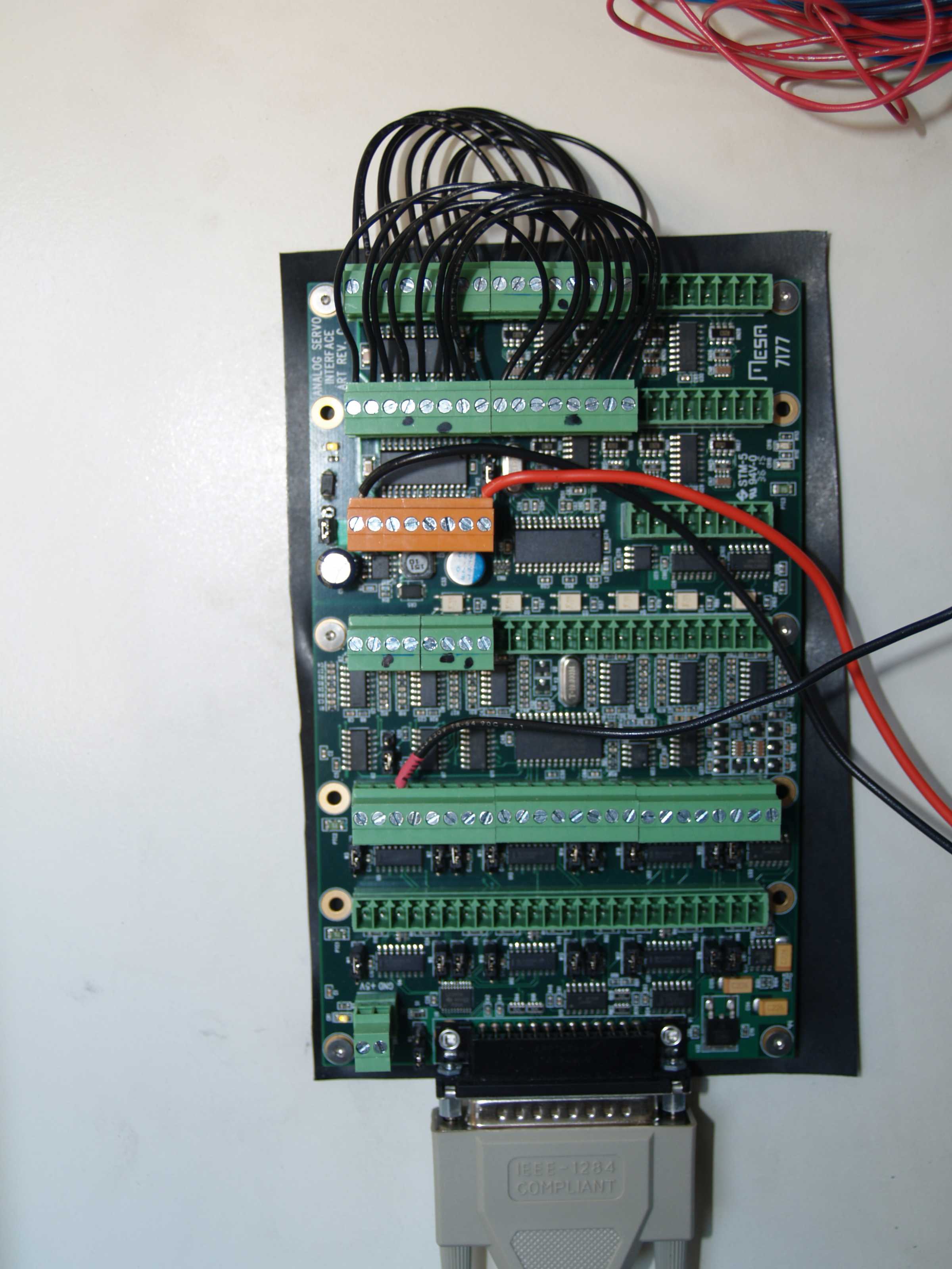
I rewrote the custom hal file to use setp and set all the hm2_5i25.0.7i77.0.0.ouput-XX pins to true. I started up linuxcnc and then measured the voltage on each output terminal screw and got the following readings:
output-00 15.55
output-01 23.82
output-02 23.82
output-03 0.02
output-04 23.82
output-05 23.82
output-06 23.82
output-07 0.01
output-08 0.33
output-09 0.37
output-10 0.36
output-11 0.24
output-12 0.37
output-13 0.57
output-14 0.41
output-15 0.23
I also edited the HAL file to turn only one bank one at a time, and the voltage measurements were exactly the same.
This is different than what I measured last night where the voltages on 08 through 15 matched the 00 - 07 voltages when I had shut off the 00 -07 outputs. When I do turn off a bank of outputs, there voltages don't measure anything over 0.01.
I am stumped as to what is causing the 7i77 to not provide voltage on the output terminals. Even ignoring the 08-15 bank, looking at just the 00 - 07 bank, one output is at half the supply voltage, and two of the outputs are at basically zero voltage.
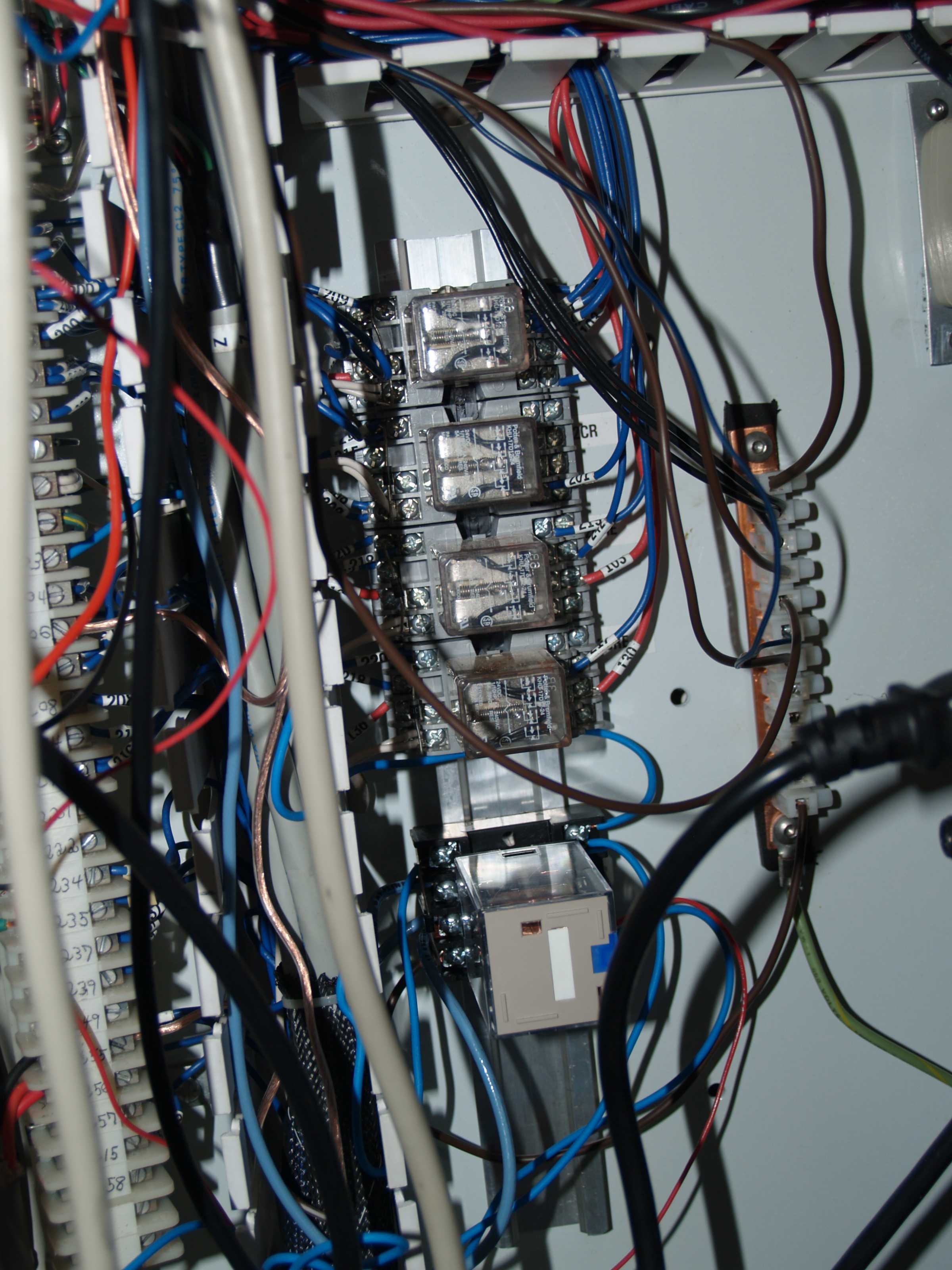
As far as my relays are concerned, all of them run around the 60 mA range and all of them have flyback diodes. The original relays retained from the Dynapath setup already had flyback diodes, and I installed a flyback diode on the one new relay I installed. See photo.
Any idea what I can check next? When I originally got the board back in May there was an issue with the terminals on TB2 being shorted. I returned the board to Mesa and they said they fixed the problem and the board was working fine. Is there a possibility that there was some other underlying problem that was not detected when Mesa served the board? I do not know if they would have run a complete quality check on the board to insure that all the inputs and outputs were working. I does concern me that terminal 2 on the TB2 connect does not measure 23.8 Vdc when I apply power to terminal pin 1. Do I need to apply input power to more than just terminal one on TB2?
I would hate to have to send the board back to Mesa if there is simply something that I am missing. I am using the 5 Vdc power through the parallel cable connecting the 7i77 to the 5125. Could that be a problem and should I install a separate 5 VDC power supply? For these last tests I have unplugged all the other terminal caps so there should be no other drain on the system.
I am completely stump and would appreciate any help you can provide.
Thanks.
Sorry if I do not fully understand all of your explanations. This level of electronics is a little out of my area of expertise. Being an ordnance engineer, if you want to design a warhead to defeat an M1A1 main battle tank, or a torpedo warhead to sink a nuclear powered Soviet attack sub, that I can do. With this electronics stuff I usually need very simple and thorough explanations.
Based upon your last message, I rewired the 7i77 board as I interpreted your explanation and the rewired board is shown in the following photo.
I rewrote the custom hal file to use setp and set all the hm2_5i25.0.7i77.0.0.ouput-XX pins to true. I started up linuxcnc and then measured the voltage on each output terminal screw and got the following readings:
output-00 15.55
output-01 23.82
output-02 23.82
output-03 0.02
output-04 23.82
output-05 23.82
output-06 23.82
output-07 0.01
output-08 0.33
output-09 0.37
output-10 0.36
output-11 0.24
output-12 0.37
output-13 0.57
output-14 0.41
output-15 0.23
I also edited the HAL file to turn only one bank one at a time, and the voltage measurements were exactly the same.
This is different than what I measured last night where the voltages on 08 through 15 matched the 00 - 07 voltages when I had shut off the 00 -07 outputs. When I do turn off a bank of outputs, there voltages don't measure anything over 0.01.
I am stumped as to what is causing the 7i77 to not provide voltage on the output terminals. Even ignoring the 08-15 bank, looking at just the 00 - 07 bank, one output is at half the supply voltage, and two of the outputs are at basically zero voltage.
As far as my relays are concerned, all of them run around the 60 mA range and all of them have flyback diodes. The original relays retained from the Dynapath setup already had flyback diodes, and I installed a flyback diode on the one new relay I installed. See photo.
Any idea what I can check next? When I originally got the board back in May there was an issue with the terminals on TB2 being shorted. I returned the board to Mesa and they said they fixed the problem and the board was working fine. Is there a possibility that there was some other underlying problem that was not detected when Mesa served the board? I do not know if they would have run a complete quality check on the board to insure that all the inputs and outputs were working. I does concern me that terminal 2 on the TB2 connect does not measure 23.8 Vdc when I apply power to terminal pin 1. Do I need to apply input power to more than just terminal one on TB2?
I would hate to have to send the board back to Mesa if there is simply something that I am missing. I am using the 5 Vdc power through the parallel cable connecting the 7i77 to the 5125. Could that be a problem and should I install a separate 5 VDC power supply? For these last tests I have unplugged all the other terminal caps so there should be no other drain on the system.
I am completely stump and would appreciate any help you can provide.
Thanks.
Please Log in or Create an account to join the conversation.
- PCW
-
- Offline
- Moderator
-
Less
More
- Posts: 17961
- Thank you received: 5265
12 Aug 2016 19:21 #78687
by PCW
Replied by PCW on topic Mesa 7i77 output voltages
There was never any problem found so we did not fix the board as it passed all tests
(TB2 was not shorted and the card passed a full input and output loopback and analog test)
Can you post your test hal file here?
If that looks OK I will issue a RMA again
(TB2 was not shorted and the card passed a full input and output loopback and analog test)
Can you post your test hal file here?
If that looks OK I will issue a RMA again
Please Log in or Create an account to join the conversation.
- jwsigler
- Offline
- Senior Member
-
Less
More
- Posts: 63
- Thank you received: 1
12 Aug 2016 20:54 #78690
by jwsigler
Replied by jwsigler on topic Mesa 7i77 output voltages
Attached is the Hal file I used to attempt to power the output terminals on TB7 and TB8. Please realize that I am just beginning to work with HAL files, but I am pretty sure I got these correct.
Of course I have no background in all these electronic components so I have no idea what, if anything, would cause this type of behavior. I searched the forum as best I could and did not find anything that appeared to apply.
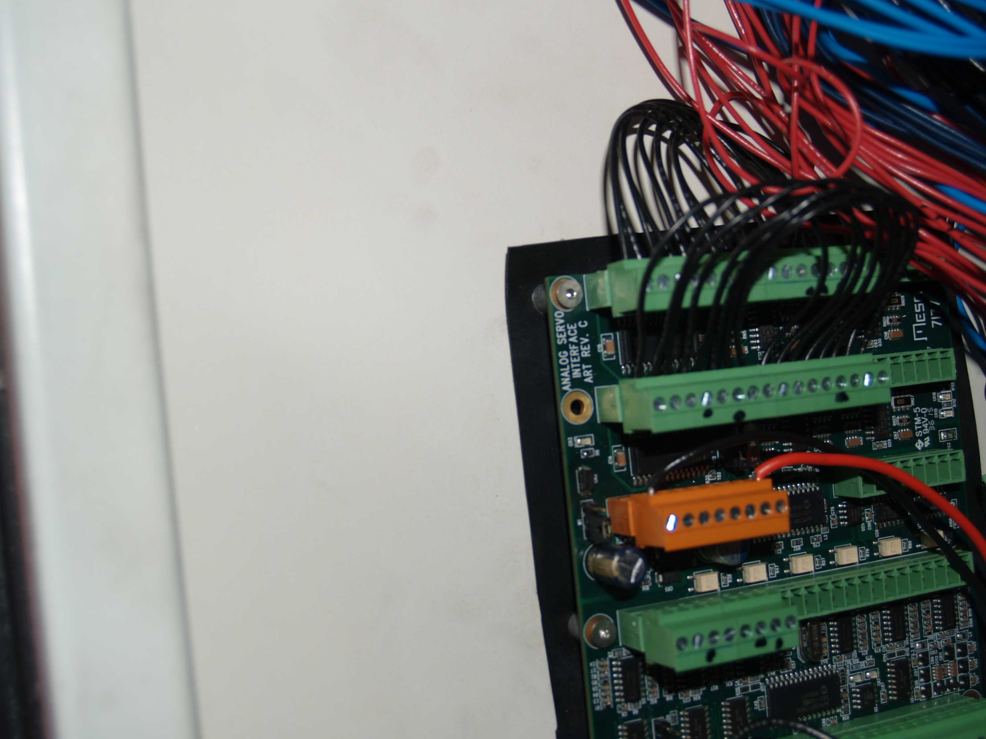
As far as the last time when I had to send this board back for repair, I was informed that the problem was a diode was bad and had to be replaced which was why TB2 was shorted. While I can blow things up better than I can design an PCB board, I can read an ohm meter adn tell when terminals are shorted. If you examine the following photo, you can see where diode CR2 has been replaced since it was soldered back into place crocked.
If there is anything else I can do to check out the issue and correct it I will be more than happy to try. I would rather avoid losing a week and a half sending the board back to the supplier for a second time, but the board does me no good if I can not get it to turn on the output channels.
As again, thank for your assistance.
Of course I have no background in all these electronic components so I have no idea what, if anything, would cause this type of behavior. I searched the forum as best I could and did not find anything that appeared to apply.
As far as the last time when I had to send this board back for repair, I was informed that the problem was a diode was bad and had to be replaced which was why TB2 was shorted. While I can blow things up better than I can design an PCB board, I can read an ohm meter adn tell when terminals are shorted. If you examine the following photo, you can see where diode CR2 has been replaced since it was soldered back into place crocked.
If there is anything else I can do to check out the issue and correct it I will be more than happy to try. I would rather avoid losing a week and a half sending the board back to the supplier for a second time, but the board does me no good if I can not get it to turn on the output channels.
As again, thank for your assistance.
Please Log in or Create an account to join the conversation.
- PCW
-
- Offline
- Moderator
-
Less
More
- Posts: 17961
- Thank you received: 5265
12 Aug 2016 22:43 #78693
by PCW
Replied by PCW on topic Mesa 7i77 output voltages
Sorry I had forgotten that the diode was shorted
This does mean that field power was applied backwards at one point
Normally this doesn't damage other components but it may have this time
This does mean that field power was applied backwards at one point
Normally this doesn't damage other components but it may have this time
Please Log in or Create an account to join the conversation.
Time to create page: 0.244 seconds