Making 0-10V output work with spindle in HAL
- sushantkurren
-
 Topic Author
- Offline
- New Member
-

Less
More
- Posts: 7
- Thank you received: 0
26 Oct 2020 06:17 #187277
by sushantkurren
Making 0-10V output work with spindle in HAL was created by sushantkurren
Hi there,
I currently have this breakout board wired up to my CNC: www.aliexpress.com/item/1801916509.html which seem to be ubiquitous over the internet.
My issue is I currently have the 0-10V + GND on the right side of the board attached to my VFD 0-10V/GND inputs.
I also have P17 connected as 'Spindle On' and have connected that to the "FWD" pin on the VFD. When I type M3 and M5 in LinuxCNC, the relay triggers (I can hear it), so that's working fine.
However when I read the documentation regarding 0-10V Spindle Control on: linuxcnc.org/docs/2.5/html/examples/spindle.html I am unable to figure out what the <your DAC pin name> would be. I am unsure what the name of the 0-10V pin would be called in the HAL and all P1-17 ports are accounted for.
Any ideas on how to wire this setup correctly or whether I should be using a different HAL setup?
Very appreciated, thank you.
Please Log in or Create an account to join the conversation.
- Aciera
-

- Offline
- Administrator
-

Less
More
- Posts: 4765
- Thank you received: 2138
26 Oct 2020 09:54 #187285
by Aciera
Replied by Aciera on topic Making 0-10V output work with spindle in HAL
Can you post your HAL and INI files?
Please Log in or Create an account to join the conversation.
- sushantkurren
-
Topic Author
- Offline
- New Member
-
Less
More
- Posts: 7
- Thank you received: 0
26 Oct 2020 10:01 #187286
by sushantkurren
Replied by sushantkurren on topic Making 0-10V output work with spindle in HAL
Here you are. Thanks
Please Log in or Create an account to join the conversation.
- Aciera
-
- Offline
- Administrator
-
Less
More
- Posts: 4765
- Thank you received: 2138
26 Oct 2020 10:20 #187288
by Aciera
Replied by Aciera on topic Making 0-10V output work with spindle in HAL
I would expect your board uses a PWM signal from one of the pins on the parallel port.
Then you would connect that pin in HAL as in the docs:
Then you would connect that pin in HAL as in the docs:
loadrt pwmgen output_type=0
addf pwmgen.update servo-thread
addf pwmgen.make-pulses base-thread
net spindle-speed-cmd motion.spindle-speed-out => pwmgen.0.value
net spindle-on motion.spindle-on => pwmgen.0.enable
net spindle-pwm pwmgen.0.pwm => parport.0.pin-09-out
# Set the spindle's top speed in RPM
setp pwmgen.0.scale 1800
Please Log in or Create an account to join the conversation.
- sushantkurren
-
Topic Author
- Offline
- New Member
-
Less
More
- Posts: 7
- Thank you received: 0
26 Oct 2020 10:25 #187289
by sushantkurren
Replied by sushantkurren on topic Making 0-10V output work with spindle in HAL
Oh great, that makes sense.
Where would the PWM then be wired into?
Where would the PWM then be wired into?
Please Log in or Create an account to join the conversation.
- Aciera
-
- Offline
- Administrator
-
Less
More
- Posts: 4765
- Thank you received: 2138
26 Oct 2020 11:57 #187298
by Aciera
Replied by Aciera on topic Making 0-10V output work with spindle in HAL
Do you have any documentation for that board?
Please Log in or Create an account to join the conversation.
- sushantkurren
-
Topic Author
- Offline
- New Member
-
Less
More
- Posts: 7
- Thank you received: 0
26 Oct 2020 13:46 #187308
by sushantkurren
Replied by sushantkurren on topic Making 0-10V output work with spindle in HAL
This is what I have on that front - not the most informative.
Please Log in or Create an account to join the conversation.
- Aciera
-
- Offline
- Administrator
-
Less
More
- Posts: 4765
- Thank you received: 2138
26 Oct 2020 14:37 - 26 Oct 2020 14:53 #187314
by Aciera
Replied by Aciera on topic Making 0-10V output work with spindle in HAL
Found another bit of information from another vendor and it looks like PWM might be meant to be fed into P1 of the parallel port:
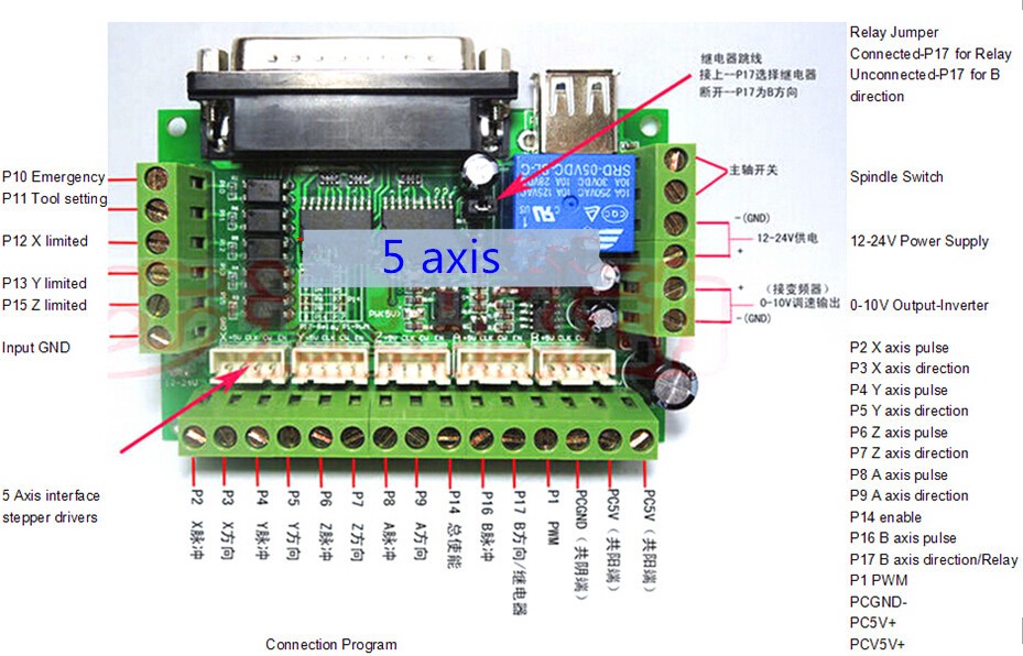
Can you actually reverse the spindle as well or is that "Spindle ON/OFF control interface" just an on/off relay contact?
[edit]
I just noticed that you use pin1 for a motor. Can you move the motors?
Ok looks like its just "Spindle ON/OFF"
Another manual: certainly looks like pin1 is the PWM
enes.ir/shop/image/catalog/Products/EN01...CNCBreakoutBoard.pdf
Attachments:
Last edit: 26 Oct 2020 14:53 by Aciera.
Please Log in or Create an account to join the conversation.
- MalteS
- Offline
- Junior Member
-

Less
More
- Posts: 33
- Thank you received: 11
26 Oct 2020 16:13 #187325
by MalteS
Replied by MalteS on topic Making 0-10V output work with spindle in HAL
This board expects PWM on Pin1. Your hal file uses Pin 9.
Make sure to connect the 12-24V on the right hand side of the board and set the jumper for P17 - Motor direction correctly.
Make sure to connect the 12-24V on the right hand side of the board and set the jumper for P17 - Motor direction correctly.
Please Log in or Create an account to join the conversation.
- sushantkurren
-
Topic Author
- Offline
- New Member
-
Less
More
- Posts: 7
- Thank you received: 0
26 Oct 2020 21:02 #187340
by sushantkurren
Replied by sushantkurren on topic Making 0-10V output work with spindle in HAL
Interesting, so are you recommending wiring the P1 PWM to "FWD" on the VFD? Or what's the idea here
Please Log in or Create an account to join the conversation.
Time to create page: 0.190 seconds