Overriding feed rate in a subroutine
- ArcEye
- Offline
- Junior Member
-

- Posts: 22
- Thank you received: 240
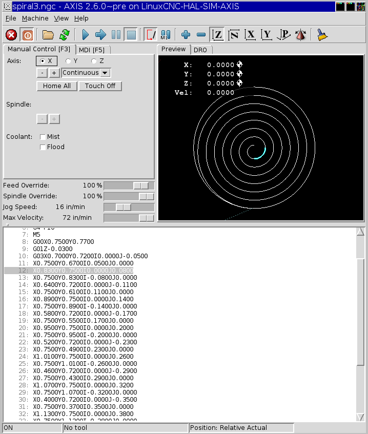
The only thing I have used a spiral for is cutting out circular pockets.
The first cut is the outside diameter and then the spiral clears the waste inside, with an increment per 360 deg just less than the cutter diameter
Please Log in or Create an account to join the conversation.
- ArcEye
- Offline
- Junior Member
-
- Posts: 22
- Thank you received: 240
Please Log in or Create an account to join the conversation.
- ArcEye
- Offline
- Junior Member
-
- Posts: 22
- Thank you received: 240
How do I rotate the coordinate system in such a way that jogging is also included? I am aware of 'G10 L2 P0 Rxx', but that doesn't work for jogging. The reason behind this: I would like to clamp a workpiece to the table without perfectly aligning it, touch off two known features, and calculate a coordinate transform. It would be nice if I can plug in a 4x4 matrix somewhere to convert workpiece coordinates to machine coordinates.
My only re-alignment is on my lathe to take account of it being a slant bed (back tool)
The jogging question does not come into it because it is 180 deg about, so down is the new up, the tool moves in the direction of the arrow keys
On my mills I use fixtures like dogs on vices that sit in the table slots, to ensure that workpieces are always aligned.
However, see JTs code for alignment of sheets on a plasma table, that works the way you are thinking of I believe
www.linuxcnc.org/index.php/english/forum...nt-in-a-plasma-table
regards
Please Log in or Create an account to join the conversation.
- DaBit
- Offline
- Elite Member
-

- Posts: 203
- Thank you received: 19
That is pretty much all I have ever done, increment or decrement the radius over a series of G2 or G3 calls
I was hoping that there was a more natural way to create a spiral, but OK.
The only thing I have used a spiral for is cutting out circular pockets.
Which is also my main purpose. I actually cut circular pockets a lot since I currently only have a high speed spindle on my (BF20/G0704) machine so i can use twist drills only up to a small size.
On my mills I use fixtures like dogs on vices that sit in the table slots, to ensure that workpieces are always aligned.
So do I, but table space on my machine is limited so often I just clamp down stock to the table, make a fixture from MDF, or use a vacuum table to hold down PCB and blocks/sheets of material.
With hand wheels it makes sense to perfectly align the workpiece, with computer control: not so. Computer can easily correct any misalignment.
However, see JTs code for alignment of sheets on a plasma table, that works the way you are thinking of I believe
Those subs save me writing my own code to do it properly (currently I am just using a handheld calculator to calculate the angle since I didn't spent the time to write a few subs yet), so they are very useful. Until you start jogging
")
On another forum the idea came up to create an extra pair of virtual rotary axes, and use them to rotate the coordinates during axis->joint transformation. Sounds like it would be only a small addition to the 'trivkins' kinematics module. And it makes creating a 'perfect spiral' a piece of cake
Sounds interesting
Please Log in or Create an account to join the conversation.
- DaBit
- Offline
- Elite Member
-
- Posts: 203
- Thank you received: 19
- Floating point P parameter. It would be nice to be able to easily program a partial circle (arc) starting from the current position, rotating with IJK coordinates as center. Currently P must be at least 1.0 (and probably an integer; didn't check that yet).
- Something like a G2.1/G3.1 which interpolates arc radius so one can start with r=10 and end with r=5 for example. Would be great for things like ellipses, spirals, HSM-like toolpaths, etc. We do have NURBS and quadratic splines, but these are not easy to program manually.
Where do I submit these?
Please Log in or Create an account to join the conversation.
- ArcEye
- Offline
- Junior Member
-
- Posts: 22
- Thank you received: 240
Please Log in or Create an account to join the conversation.
- andypugh
-

- Offline
- Moderator
-

- Posts: 19879
- Thank you received: 4643
On another forum the idea came up to create an extra pair of virtual rotary axes, and use them to rotate the coordinates during axis->joint transformation. Sounds like it would be only a small addition to the 'trivkins' kinematics module.
wiki.linuxcnc.org/cgi-bin/wiki.pl?Contri...y_XY_skew_correction
Please Log in or Create an account to join the conversation.
- andypugh
-
- Offline
- Moderator
-
- Posts: 19879
- Thank you received: 4643
Once more about arcs. I would like to submit some 'feature requests':
- Floating point P parameter. It would be nice to be able to easily program a partial circle (arc) starting from the current position, rotating with IJK coordinates as center. Currently P must be at least 1.0
Actually, "P" is a LinuxCNC add-on to the standard arc-code, and the way to do a partial circle is to have no P at all.
You have to specify end-point, not angle, though.
If you want to define moves by angle and radius, have a look at:
linuxcnc.org/docs/html/gcode/overview.html#_polar_coordinates
Please Log in or Create an account to join the conversation.
- DaBit
- Offline
- Elite Member
-
- Posts: 203
- Thank you received: 19
ContributedComponents#millkins_trivial_kinematics_extended_by_XY_skew_correction
Might be just what I think I want, although I suppose the coordinates entering kinematicsForward and kinematicsInverse are 'machine' coordinates and not 'workpiece' (G54 etc) coordinates?That might be a little awkward since modifying 'skew' would also modify workpiece zero.
Is it OK to set the millkins.skew pin at runtime from GladeVCP?
You have to specify end-point, not angle, though.
Which isn't very intuitive except for trivial cases such as a 90-degree axis-aligned arc.
If you want to define moves by angle and radius, have a look at:
linuxcnc.org/docs/html/gcode/overview.html#_polar_coordinates
I am aware of those. The (badly written) piece of sample code in post #37744 on the previous page also uses them.
The problem I have with polar coordinates is that they act from the current XY zero position. Great for bolt circles, but otherwise? It would be more useful if @ and ^ acted from a given set of coordinates (I and J, for example).
Of course there are workarounds: G92/G92.1 should work to setup a temporary origin for @ and ^ for example.
Please Log in or Create an account to join the conversation.
- andypugh
-
- Offline
- Moderator
-
- Posts: 19879
- Thank you received: 4643
Is it OK to set the millkins.skew pin at runtime from GladeVCP?
It will work. By which I mean that it is an input pin and the data is used "live".
You might need to limit the rate of change of the value to avoid following errors, either as Python code in the VCP or using the HAL "limit3" component.
Please Log in or Create an account to join the conversation.