Gantry with two different size motors on X-axis
- kemes
- Offline
- New Member
-

Less
More
- Posts: 7
- Thank you received: 0
05 Jan 2016 21:26 #67938
by kemes
Gantry with two different size motors on X-axis was created by kemes
Hi,
I've been reading this forum for a long time and I've learned so much. Thank you for all of you who do the LinuxCNC development work and for all of you people for sharing your projects and tips on the forum.
I've been running a gantry style plasma setup with one motor on each axis. Recently I added an second motor to the other end of the X-axis. The second motor on the X-axis smaller than the first one. The first X-axis motor is belt driven and the new second one has an inlineskate wheel attached to it which is running against the steel frame (spring loaded).
I've been looking at the threads which contain information about using two motors on the same axis (e.g. gantrykins) but so far I have not found a thread which would cover this topic: using to different size motors / pulleys on the same axis.
So to sum up: what would be a good way of running a system which has two different size motors / pulleys on the same axis?
Please Log in or Create an account to join the conversation.
- LearningLinuxCNC
-

- Offline
- Elite Member
-

Less
More
- Posts: 226
- Thank you received: 39
06 Jan 2016 04:19 #67946
by LearningLinuxCNC
Replied by LearningLinuxCNC on topic Gantry with two different size motors on X-axis
I believe this will require a custom kinematics. You will need to use two joints, one for each drive of the x-axis, the differential gearing will need to be figured in the kinematics file to make it work correctly.
I would try to get it to work so that both drives are the same gear ratio anyway. Should not make much difference if the motor is smaller as long as it has the same steps per inch. Then you can use gantrykins or trivkins.
I would try to get it to work so that both drives are the same gear ratio anyway. Should not make much difference if the motor is smaller as long as it has the same steps per inch. Then you can use gantrykins or trivkins.
Please Log in or Create an account to join the conversation.
- Rick G
-
- Offline
- Junior Member
-

Less
More
- Posts: 27
- Thank you received: 114
06 Jan 2016 08:25 - 06 Jan 2016 08:26 #67950
by Rick G
Replied by Rick G on topic Gantry with two different size motors on X-axis
If you create a separate step generator for the new motor with the proper parameters for it, step size direction, etc. and it can be set to match the acceleration and velocity of the the main motor you may be able to link them together in hal.
So basically feed 2 step generators from one signal. I assume there will not be separate home/limit switches?
Rick g
So basically feed 2 step generators from one signal. I assume there will not be separate home/limit switches?
Rick g
Last edit: 06 Jan 2016 08:26 by Rick G.
Please Log in or Create an account to join the conversation.
- cncbasher
- Offline
- Moderator
-

Less
More
- Posts: 1021
- Thank you received: 202
06 Jan 2016 09:27 #67952
by cncbasher
Replied by cncbasher on topic Gantry with two different size motors on X-axis
very simply ,electronics can't compete over mechanics , get the mechanics correct and working well, use identical systems each end , as you have it , is asking for trouble. you'll spend more time chasing problems than using the machine .
as it is there will be times it works fine , and others where it hounds you
so spend a little and solve this properly .
as it is there will be times it works fine , and others where it hounds you
so spend a little and solve this properly .
Please Log in or Create an account to join the conversation.
- kemes
- Offline
- New Member
-
Less
More
- Posts: 7
- Thank you received: 0
06 Jan 2016 10:44 #67959
by kemes
Replied by kemes on topic Gantry with two different size motors on X-axis
Thank you for the answers everybody! Based on your answers I think I'm going to try to mach the gear ratios between the X-axis motors and run the system just as XXZY (actually XYZA). I guess this way it's going to be impossible to get both sides of the X-axis to run smoothly through the whole range of the movement. One side will probably run faster/slower than the other side.
One thing which I did not mention in my first mail that the X-axis has one linear rail on the other end and the second end has a steel profile + bearings type of rail. The structure is like this because the X-axis is 2 meters long -> profile+bearings on the other end can handle the possible parallel misalignment on the frame.
One thing which I did not mention in my first mail that the X-axis has one linear rail on the other end and the second end has a steel profile + bearings type of rail. The structure is like this because the X-axis is 2 meters long -> profile+bearings on the other end can handle the possible parallel misalignment on the frame.
Please Log in or Create an account to join the conversation.
- andypugh
-

- Offline
- Moderator
-
Less
More
- Posts: 19875
- Thank you received: 4642
06 Jan 2016 10:51 #67960
by andypugh
Are you saying that the extra axis is friction-drive?
That won't work, it is bound to creep and end up out of synch with the geared drive.
Replied by andypugh on topic Gantry with two different size motors on X-axis
I've been running a gantry style plasma setup with one motor on each axis. Recently I added an second motor to the other end of the X-axis. The second motor on the X-axis smaller than the first one. The first X-axis motor is belt driven and the new second one has an inlineskate wheel attached to it which is running against the steel frame (spring loaded).
Are you saying that the extra axis is friction-drive?
That won't work, it is bound to creep and end up out of synch with the geared drive.
Please Log in or Create an account to join the conversation.
- Todd Zuercher
-

- Away
- Platinum Member
-

Less
More
- Posts: 4757
- Thank you received: 1459
06 Jan 2016 14:38 #67967
by Todd Zuercher
Replied by Todd Zuercher on topic Gantry with two different size motors on X-axis
I think pictures of what exactly you have going on may be very helpful. As to having different gearing/side, that should be easily compensated for in hal. It is your overall mechanics that sound rather questionable.
What I'm trying to fathom is why in the world you would even want to have different drive motors and mechanics on either end of a gantry.
What I'm trying to fathom is why in the world you would even want to have different drive motors and mechanics on either end of a gantry.
Please Log in or Create an account to join the conversation.
- andypugh
-
- Offline
- Moderator
-
Less
More
- Posts: 19875
- Thank you received: 4642
06 Jan 2016 14:46 #67969
by andypugh
In theory you could use strain-gauges on the gantry beam to drive the auxiliary motor in closed-loop control to keep the gantry straight.
Replied by andypugh on topic Gantry with two different size motors on X-axis
What I'm trying to fathom is why in the world you would even want to have different drive motors and mechanics on either end of a gantry.
In theory you could use strain-gauges on the gantry beam to drive the auxiliary motor in closed-loop control to keep the gantry straight.
Please Log in or Create an account to join the conversation.
- kemes
- Offline
- New Member
-
Less
More
- Posts: 7
- Thank you received: 0
06 Jan 2016 17:45 #67975
by kemes
Replied by kemes on topic Gantry with two different size motors on X-axis
Yes, the second drive is a friction one. A big NO NO, I know.
I know this is not the best setup to go with. My first intention was to use only three stepper motors (single sided motor on the X-axis). When I realized that the the X-axis was not stable enough I ended up installing the second stepper to the other end of the X-axis as an "assistant motor" to stabilize the axis. And now I'm here. I've learned my lesson, the next design will have two motors or an axle to the other side (either way similar gear ratios and driven from both sides). I think my choices basically are: renew the frame/axis design, stiffen up the X-axis and stick with the original single sided plan OR get the second stepper configured on the X-axis.
I guess there are a few complex choices to configure the second stepper on the X-axis, I have to dive a bit deeper into the configuration of LCNC to understand how to get things working.
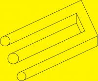
I should have photos, sorry about this. Unfortunately the plasma is not where I'm at the moment. Here is a screencap of the CAD model of the overall setup (table size 1x2 meters):

I know this is not the best setup to go with. My first intention was to use only three stepper motors (single sided motor on the X-axis). When I realized that the the X-axis was not stable enough I ended up installing the second stepper to the other end of the X-axis as an "assistant motor" to stabilize the axis. And now I'm here. I've learned my lesson, the next design will have two motors or an axle to the other side (either way similar gear ratios and driven from both sides). I think my choices basically are: renew the frame/axis design, stiffen up the X-axis and stick with the original single sided plan OR get the second stepper configured on the X-axis.
I guess there are a few complex choices to configure the second stepper on the X-axis, I have to dive a bit deeper into the configuration of LCNC to understand how to get things working.
I should have photos, sorry about this. Unfortunately the plasma is not where I'm at the moment. Here is a screencap of the CAD model of the overall setup (table size 1x2 meters):
Please Log in or Create an account to join the conversation.
- Todd Zuercher
-
- Away
- Platinum Member
-
Less
More
- Posts: 4757
- Thank you received: 1459
06 Jan 2016 18:11 #67976
by Todd Zuercher
Replied by Todd Zuercher on topic Gantry with two different size motors on X-axis
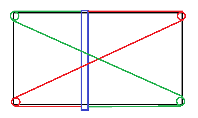
Maybe you could use some cable or steel banding with some pulleys to keep the gantry square while only driving one side. Kind of like this.
Please Log in or Create an account to join the conversation.
Time to create page: 0.159 seconds