How to and2 the probe input with a digital input
- Waldemar
-
 Topic Author
- Offline
- Junior Member
-

- Posts: 34
- Thank you received: 11
Apologies for the rudimentary nature of this question, but I'm really green with this and need a bit of a push in the right direction.
So I have a basic Z-probe set up (and by and large working). I get the odd spurious trip on the probe input when not probing, so I'd like to have the probe input active ONLY whilst probing. I've spotted a post on the forum where the simple solution to achieve this is to
and.2 the probe input with a digital input and in your gcode probing routine issue a M67 or M68 command to turn the input on and off.
OK, so I think that by using the and.2 you effectively need 2 TRUE values for the probe input to be on - one of the inputs is the actual analogue probe (by default on its own always on) and the other input (the digital one) can be turned on/off using the M67 / M68 command thereby forcing the analogue probe input to follow its lead.
Firstly am I correct in thinking this is what's going on - and secondly, how would this look in the context of both .hal and gcode file/subroutine.
Again, sorry for the basic nature of this query - I'm a monkey see / monkey do kinda guy...
Wal.
Please Log in or Create an account to join the conversation.
- Waldemar
-
 Topic Author
- Offline
- Junior Member
-

- Posts: 34
- Thank you received: 11
Anyway, I came across this post earlier:
forum.linuxcnc.org/24-hal-components/423...rrors?start=0#269004
ok's post would suggest that using and2 wouldn't work anyway, contrary to what others have suggested - is that true? Is it worth me pursuing (I'm banging my head against the wall a bit with this as there don't seem to be many real world examples for non-codey people like me on how to set this up and trust me - I've read and re-read the bits that should be helpful to me!) - or do I just learn to live with the odd probe error?
Wal.
Please Log in or Create an account to join the conversation.
- tommylight
-

- Away
- Moderator
-

- Posts: 21198
- Thank you received: 7241
-
Probe tripping at random is a wiring/signaling/grounding/shielding issue.
Sorry to have to say this, but seeking software solutions for hardware issues is never ever a good idea.
I mainly build plasma machines, those do huge amounts of interference, but i never ever used debounce on inputs.
Please Log in or Create an account to join the conversation.
- Waldemar
-
 Topic Author
- Offline
- Junior Member
-

- Posts: 34
- Thank you received: 11
It's not a random issue now - I sorted out the grounding by connecting the 24VDC common neutral to the control box frame ground - I'm told that technically this is bad practice BUT all of the random triggers have disappeared along with the noise on the probe's cable when the VFD was running. (Generally speaking my box and the cables etc have been shielded pretty well.)
My issue (Probe tripped during non-probe move) happens only occasionally when the tip of the end mill is coming off the touch off surface - which will usually be a bit of scrap that gets faced off to correspond with work on the table.
Sorry to have to say this, but seeking software solutions for hardware issues is never ever a good idea.
And I totally agree with you, but this appears to be a problem that many senior forum members have faced and apparently solved in software. Take Andy Pugh's DIY probe - it still needed a software fix for the mechanical bounce and rodw suggests a couple of software fixes for the problem here:
forum.linuxcnc.org/24-hal-components/423...rrors?start=0#269052
and repeats the and2 fix here:
forum.linuxcnc.org/24-hal-components/423...rrors?start=0#217796
The issue I'm up against is not having the knowledge to be able to implement rodw's simple enough sounding advice:
and:When I faced this, I modified my probing gcode routine to set a digital output true from gcode and false after probing.
Then you can and2 the probe output with the digital output before connecting to motion.probe-input.
(I do believe that both snippets above relate to the same solution, just expressed differently...) What I'd dearly like to see is a snippet from somebody's .hal and/or gcode files with maybe a couple of pointers thrown in that give me a bit more of a chance to understand how to to set this up. Or is is that considered cheating?!When I had this issue I and2'ed the probe signal to a digital output and added m62-m65 to my probe routine so the probe would only trigger if the digital output was true (during probing).
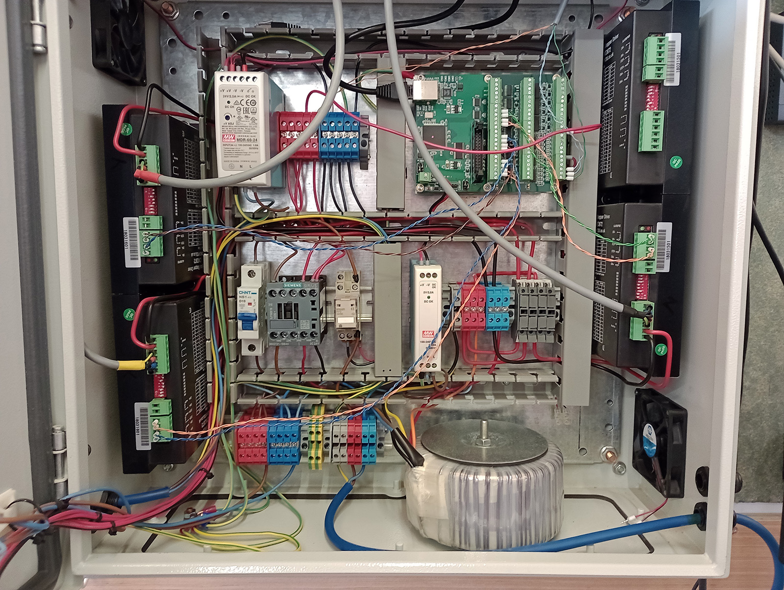
You did ask for pics of probe and control box - they don't serve any real purpose as the noise issues are sorted and my question is really about modifying the .hal file, but here they are anyway.
Wal.
Attachments:
Please Log in or Create an account to join the conversation.
- tommylight
-

- Away
- Moderator
-

- Posts: 21198
- Thank you received: 7241
Juts to clarify, you mean the DC side 0V or - or GND side of the DC output, right?I sorted out the grounding by connecting the 24VDC common neutral to the control box frame ground - I'm told that technically this is bad practice BUT all of the random triggers have disappeared....
That should be grounded for noisy installations, always, all power supplies i had till 2016 had this tied to ground inside the power supply, some new ones do not but some still do.
Hell, even laptop power supplies with 3 prongs usually (again, before, always) have the 0V side tied to ground.
Even bigger hell, my Mazak has that tied to the case/chassis/all 3.5 tons of metal, uses sinking sensors/switches and stuff so everything goes to ground, worked with the original control, works with Mesa and LinuxCNC without issues.
All this is as i do not get it who would say that is a bad practice, except if there is no grounding anywhere and no option for providing it. Only in this case it might be better not tying it to ground as the chassis/case would act like an antenna.
---BUT, if you mean the neutral on the line power side, that is never ever a good idea. If this is not the case, please do not refer to" - or 0V or GND " as "neutral" ever, that sent shivers down my spine, bad sh1t can happen...
-
I do understand the confusion as this "internet experts" naming stuff at random to look smart has gotten out of hand, -V is negative voltage, 0V is common, +V is positive, that is it. Naming 0V as -24V is wrong always as power supplies can have negative voltages so for us in electronics seeing +24V and -24V is always 48V, naming it GND is OK only if it is actually tied to ground, but not dangerous or wrong per se.
Sorry for the long winded reply, but no neutral, please.
Please Log in or Create an account to join the conversation.
- tommylight
-

- Away
- Moderator
-

- Posts: 21198
- Thank you received: 7241
Probably can be solved with de bounce, so now i am confused (still terrified by the above), do you have a single probe or several?My issue (Probe tripped during non-probe move) happens only occasionally when the tip of the end mill is coming off the touch off surface - which will usually be a bit of scrap that gets faced off to correspond with work on the table.
For a single probe you do not need and2, that was "solving hardware issues with software" part, to disable probe triggering when not actually probing.
Please Log in or Create an account to join the conversation.
- Waldemar
-
 Topic Author
- Offline
- Junior Member
-

- Posts: 34
- Thank you received: 11
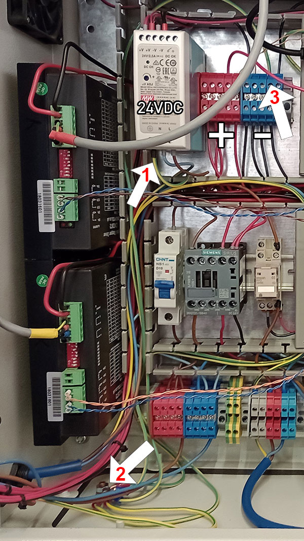
Heh - sorry - no, I didn't mean that. See the attached pic.BUT, if you mean the neutral on the line power side, that is never ever a good idea.
To the right of the 24VDC PS I have the common positive & negative terminals that come off that supply. The earth on the AC side of the 24VDC supply (arrow 1) is connected to frame ground (arrow 2), and so is the green and yellow wire coming off the common negative terminals (arrow 3). Frame ground also has the earth coming in from the AC mains attached to it - and this is what I'm told is bad practice (DC and AC sharing earth). Having said that, connecting that 24VDC common negative terminal to the frame ground solved ALL of the noise issues that the addition of the probe & its wires had introduced.
Wal.
Attachments:
Please Log in or Create an account to join the conversation.
- Waldemar
-
 Topic Author
- Offline
- Junior Member
-

- Posts: 34
- Thank you received: 11
Yes, I've been told that debounce would be something to look at also. The and2 method that rodw suggests is (as I understand it) just combining a digital output (controllable via gcode) with the actual probe output - because and2 needs two TRUE values to output a TRUE value this means that the probe output can be turned off immediately after the probing is complete and thereby preventing the error from ever occurring. BUT user OK posted the following:
As I wrote, I saw the probe errors even though I gated the (cheap) probe with and2 as you suggested. And after reading the relevant source, I think that is also to be expected, as the probe status might jiggle around after the probing is done but whilst the motion controller is still in probing mode, as those are two different state flags. This jigging can then trigger an error from the probe routine. I didn't try to check the motion.motion-type method but because of this, I'd expect it to not solve that problem either.
Which suggests that rodw's solutions have a good chance of not working (although there's always the chance that OK implemented them incorrectly).
Another method suggested by rodw is:
Another robust component based approach would be to read motion.motion-type and only output a probe output when it equals 5.
Which also seems like a very plausible approach.
So - the good news is that there are three seemingly available solutions via software, the bad news is that I haven't been able to work out how to try any of 'em. If you (or anyone!) could elucidate me on how to get any of these set up in my .hal file that would be amazing.
Regarding debounce - is this info still relevant?
www.forum.linuxcnc.org/24-hal-components...ounce-to-probe#91307
Wal.
Please Log in or Create an account to join the conversation.
- tommylight
-

- Away
- Moderator
-

- Posts: 21198
- Thank you received: 7241
Please Log in or Create an account to join the conversation.
- Waldemar
-
 Topic Author
- Offline
- Junior Member
-

- Posts: 34
- Thank you received: 11
Wal.
Please Log in or Create an account to join the conversation.


