Repair Servodrive Yaskawa CACR
- aleksamc
-
 Topic Author
- Offline
- Platinum Member
-

Less
More
- Posts: 569
- Thank you received: 67
29 Mar 2021 10:37 - 29 Mar 2021 10:40 #204010
by aleksamc
Replied by aleksamc on topic Repair Servodrive Yaskawa CACR
1. Input voltage is 300Vdc because of rectified 220Vac.
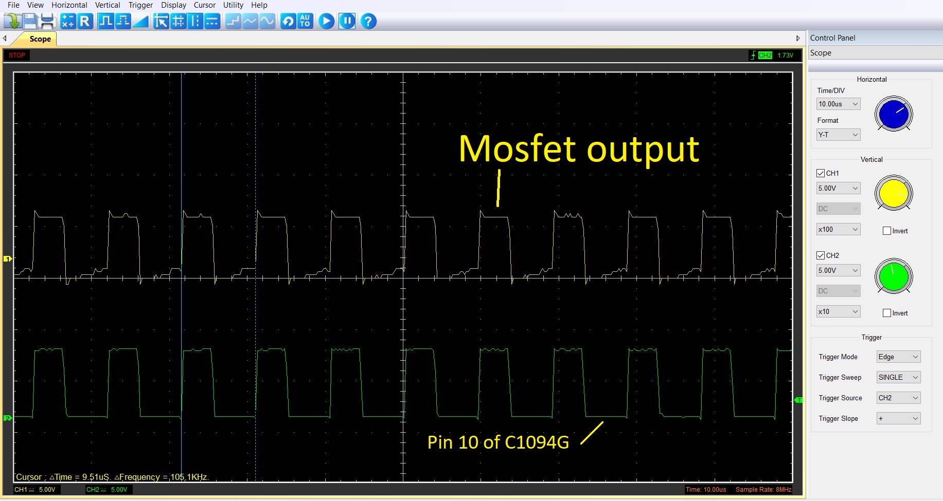
2. I didn't measure voltage at pin 9 but I previously uploaded photo of osciloscope value at pin 10 and mosfet output, they are controlable.
3. Voltage at pin 8 as I wrote is 9.3V. Look my uploaded video, there is seen that when voltage (green) incease, pulses are stop and voltage fall down to some value, then all repeats.
3x75Kohm,5w are connected seriesly.
I have changed resistor 4,7kOhm, it connected to anode of zener diod ZD1 that was shorted at first time and GND of pin 7 of IC. Other side of the resistor is connected to pin 3 (output) of the Mosfet.
This resistor was shortcur cuited, it's fo sure.
Last edit: 29 Mar 2021 10:40 by aleksamc.
Please Log in or Create an account to join the conversation.
- sivaraj
- Offline
- Senior Member
-

Less
More
- Posts: 50
- Thank you received: 25
29 Mar 2021 10:52 - 29 Mar 2021 10:52 #204012
by sivaraj
Replied by sivaraj on topic Repair Servodrive Yaskawa CACR
From osciloscope I see that I have 105kHz pulse period in datasheet pulse period 50.. 500kHz.
Need I increase oscilating freaquency to get stable work?
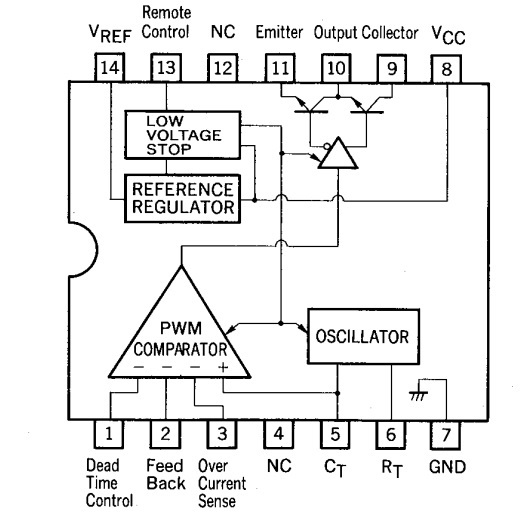
this frequency is decided by CT & RT on pin 5 & 6 .
Never change its values . It should have exact same values as original even if you replace .
This frequency will be a variable based on feedback at pin 2
Last edit: 29 Mar 2021 10:52 by sivaraj.
Please Log in or Create an account to join the conversation.
- sivaraj
- Offline
- Senior Member
-
Less
More
- Posts: 50
- Thank you received: 25
29 Mar 2021 10:58 - 29 Mar 2021 11:34 #204013
by sivaraj
I see two condition which does not allow to work normal .
.undervolage- 9.3v
or
there is no voltage feedback at pin-2 at start up. during startup pulses you are observing there should be a feedback at pin-2 to hold the oscillator
Have you confirmed there is no short circuit between 5v & PG comparing with good PCB ?
With short duration of pulses at pin-10 , if mosfet is good it had switched the primary transformer. so you must see some output voltage on 5V during pulse output . or mosfet is not working ?
Replied by sivaraj on topic Repair Servodrive Yaskawa CACR
1. Input voltage is 300Vdc because of rectified 220Vac.
2. I didn't measure voltage at pin 9 but I previously uploaded photo of osciloscope value at pin 10 and mosfet output, they are controlable.
3. Voltage at pin 8 as I wrote is 9.3V. Look my uploaded video, there is seen that when voltage (green) incease, pulses are stop and voltage fall down to some value, then all repeats.
3x75Kohm,5w are connected seriesly.
I have changed resistor 4,7kOhm, it connected to anode of zener diod ZD1 that was shorted at first time and GND of pin 7 of IC. Other side of the resistor is connected to pin 3 (output) of the Mosfet.
This resistor was shortcur cuited, it's fo sure.
I see two condition which does not allow to work normal .
.undervolage- 9.3v
or
there is no voltage feedback at pin-2 at start up. during startup pulses you are observing there should be a feedback at pin-2 to hold the oscillator
Have you confirmed there is no short circuit between 5v & PG comparing with good PCB ?
With short duration of pulses at pin-10 , if mosfet is good it had switched the primary transformer. so you must see some output voltage on 5V during pulse output . or mosfet is not working ?
Last edit: 29 Mar 2021 11:34 by sivaraj.
Please Log in or Create an account to join the conversation.
- aleksamc
-
Topic Author
- Offline
- Platinum Member
-
Less
More
- Posts: 569
- Thank you received: 67
29 Mar 2021 11:44 - 29 Mar 2021 15:46 #204016
by aleksamc
Replied by aleksamc on topic Repair Servodrive Yaskawa CACR
I've read osciloscope value from working one device, here it is.
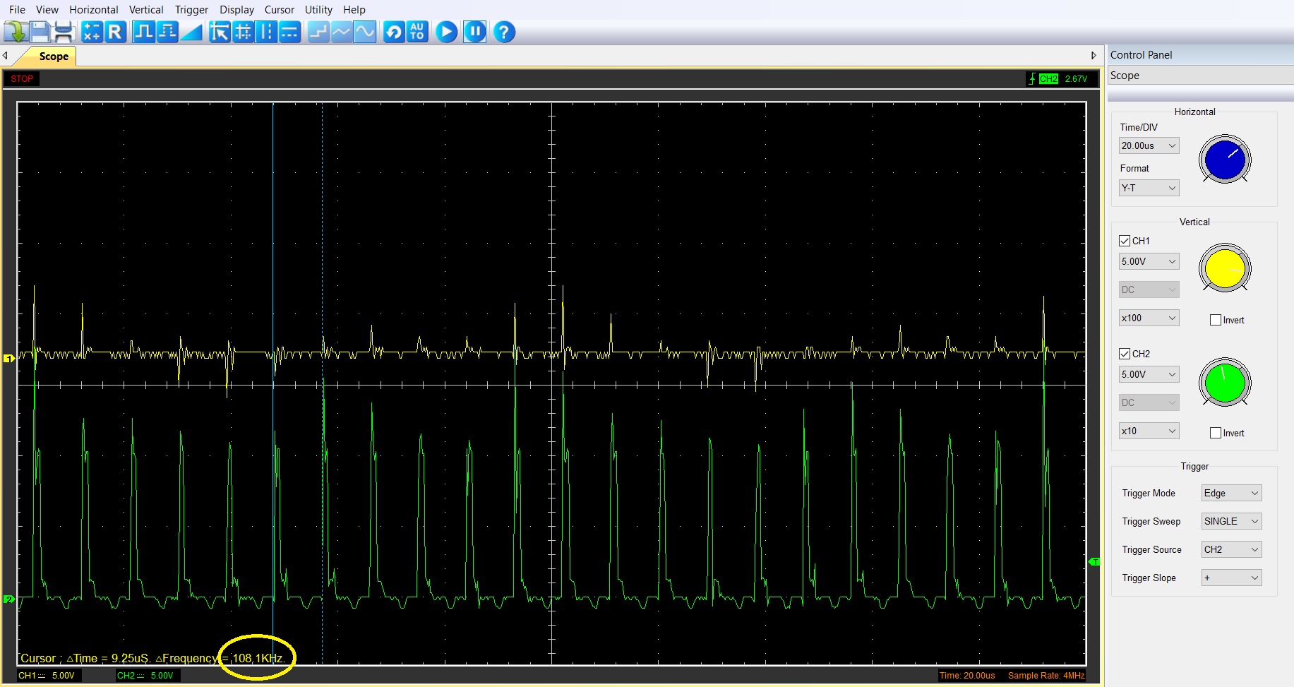
In comparing with broken one, I attach picture down.
You can see that period pulse of working one is much shorter, moreover it even not open mosfet...
In comparing with broken one, I attach picture down.
You can see that period pulse of working one is much shorter, moreover it even not open mosfet...
Last edit: 29 Mar 2021 15:46 by aleksamc.
Please Log in or Create an account to join the conversation.
- aleksamc
-
Topic Author
- Offline
- Platinum Member
-
Less
More
- Posts: 569
- Thank you received: 67
30 Mar 2021 19:49 #204142
by aleksamc
Replied by aleksamc on topic Repair Servodrive Yaskawa CACR
I wrote a lot information previously, may be it's hard to read all that information.
I measured Pin 1 to GND signal. When pulses starts to generate, this voltage fall down and pulses stops.
I really don't anderstand why VCC-Gnd voltage is so low, only 9.3V.
I don't anderstand it complitly.
Possibly I need to look for some new servodrive.
I measured Pin 1 to GND signal. When pulses starts to generate, this voltage fall down and pulses stops.
I really don't anderstand why VCC-Gnd voltage is so low, only 9.3V.
I don't anderstand it complitly.
Possibly I need to look for some new servodrive.
Please Log in or Create an account to join the conversation.
- arvidb
-

- Offline
- Platinum Member
-
Less
More
- Posts: 459
- Thank you received: 158
30 Mar 2021 23:05 #204157
by arvidb
So maybe focus on what's connected to pins 1 and 2, and try to draw a better schematic of that part of the circuit? Especially since you had to replace some parts there. Maybe your new zener is a few volts off after all? When you compared to the zener in a working driver, how did you measure its zener voltage?
Replied by arvidb on topic Repair Servodrive Yaskawa CACR
So the circuit seems to almost do what it's supposed to do, but the feedback is wrong so it turns off too early?Look my uploaded video, there is seen that when voltage (green) incease, pulses are stop and voltage fall down to some value, then all repeats.
So maybe focus on what's connected to pins 1 and 2, and try to draw a better schematic of that part of the circuit? Especially since you had to replace some parts there. Maybe your new zener is a few volts off after all? When you compared to the zener in a working driver, how did you measure its zener voltage?
Please Log in or Create an account to join the conversation.
- sivaraj
- Offline
- Senior Member
-
Less
More
- Posts: 50
- Thank you received: 25
31 Mar 2021 09:40 - 31 Mar 2021 10:25 #204195
by sivaraj
Replied by sivaraj on topic Repair Servodrive Yaskawa CACR
I also feel something wrong with feedback sensing or output circuit.
As per reference circuit Pin-14 is reference voltage to the circuit .
You have mentioned 5v is there on pin-14 .
So this is fine .
Pin-1 is dead time control .This receives a control voltage through a potentiometer (50k in reference circuit) .
I see there is a pot in the PCB to adjust 5v mostly this one connected to pin-1 of IC to adjust dead time control.
Pin-2 is for feedback confirms output voltage is ON.According to circuit it will become 5V if there is senses of output feedback.
You may need to trace this circuit.
Though minimum VCC is 11v , your circuit tries to start but stops due to
either 1.under voltage or 2.No feedback received or 3.over current sense.
Please check these three pins 1,2&3 waveform with good working one to get better idea.
Also observe two secondary coil outputs- one for output 5V and another feeds supply to VCC.
There should be some pulse here whenever startup pulses present to mosfet
In the reference circuit you can see there is a additional supply to VCC derived through a diode from one secondary coil .It looks this VCC voltage will increase to typical voltage once transformer circuit starts working and gets additional voltage through this .
If dc supply present ,transformer is good and mosfet is working obviously there should be a output voltage change for the short train of pulses you observe .but it does not happen in your case.
Worst case I would suggest this .
You may use an external smps of 5v to test (rated like input 200vac to 5vdc).
Isolate the onboard 5V circuit on secondary side( diode from secondary ) .
directly apply 5V from external 5V .
It may work . 5V mainly used for processor circuit .
For example this may replace your current circuit www.meanwell.com/productPdf.aspx?i=399#1.
It accepts either input 264vac or 374Vdc .If you get this kind of supply just use 300vdc DC input supply from onboard and connect 5v from external supply to 5v circuit. Ensure to cut connection to the onboard supply 5V circuit.
But I see your PCB got another section of power supply.
May be it is for +/-15 or 12v, any interlock with these which I am not sure
Last edit: 31 Mar 2021 10:25 by sivaraj.
Please Log in or Create an account to join the conversation.
- sivaraj
- Offline
- Senior Member
-
Less
More
- Posts: 50
- Thank you received: 25
31 Mar 2021 12:10 - 31 Mar 2021 12:36 #204208
by sivaraj
can you please redraw the ZD1 and 4.7k circuit ?
In previously hand drawn circuit ZD1 diode direction is wrong.
It show a 18k resistor on pin 1 connects to ZD1 ?
I read in above message that you have mentioned one leg of 4.7k resistor is connected to pin 3 (output) of the Mosfet.
Is this 300Vdc ? I assume this is Source leg of mosfet connects to primary transformer to dc bus voltage .
Does it mean zener makes 12.5v(as per good working condition drive ) from the 300Vdc.
Is this Zener cathode leg track directly connected to VCC of IC.
If it is so this 4.7k resistor value is wrong .Your actual circuit is not as per reference circuit .
It is a modified circuit. My another assumption here is that VCC supply to IC is derived through this 4.7K and ZD1
The <473> you have used on hand drawn schematic is a nearby capacitor value .It is actually rating of C51 capacitor.
I assume it is a ground track which connects to C81 capacitor negative leg and and anode of ZD1.
But if I assume 473 as ground track , in 3places you have used, circuit does not make any sense
How the cathode of ZD1 connected ?
Replied by sivaraj on topic Repair Servodrive Yaskawa CACR
1. Input voltage is 300Vdc because of rectified 220Vac.
I have changed resistor 4,7kOhm, it connected to anode of zener diod ZD1 that was shorted at first time and GND of pin 7 of IC. Other side of the resistor is connected to pin 3 (output) of the Mosfet.
This resistor was shortcur cuited, it's fo sure.
can you please redraw the ZD1 and 4.7k circuit ?
In previously hand drawn circuit ZD1 diode direction is wrong.
It show a 18k resistor on pin 1 connects to ZD1 ?
I read in above message that you have mentioned one leg of 4.7k resistor is connected to pin 3 (output) of the Mosfet.
Is this 300Vdc ? I assume this is Source leg of mosfet connects to primary transformer to dc bus voltage .
Does it mean zener makes 12.5v(as per good working condition drive ) from the 300Vdc.
Is this Zener cathode leg track directly connected to VCC of IC.
If it is so this 4.7k resistor value is wrong .Your actual circuit is not as per reference circuit .
It is a modified circuit. My another assumption here is that VCC supply to IC is derived through this 4.7K and ZD1
The <473> you have used on hand drawn schematic is a nearby capacitor value .It is actually rating of C51 capacitor.
I assume it is a ground track which connects to C81 capacitor negative leg and and anode of ZD1.
But if I assume 473 as ground track , in 3places you have used, circuit does not make any sense
How the cathode of ZD1 connected ?
Last edit: 31 Mar 2021 12:36 by sivaraj.
The following user(s) said Thank You: aleksamc
Please Log in or Create an account to join the conversation.
- aleksamc
-
Topic Author
- Offline
- Platinum Member
-
Less
More
- Posts: 569
- Thank you received: 67
31 Mar 2021 19:09 #204266
by aleksamc
Replied by aleksamc on topic Repair Servodrive Yaskawa CACR
Yes, Sivaraj, your all assumtions are right.
More over, I found today, that on the workable servodrive, this resistor (4.7kOhm) is also short curcuited! So, never belive what you see.
I was so tired from this servo and fall in complite frustration from resistor.
I found company in my country that positionate them as master company that could repair servodrives. So I send them today my broken and workable servos. I hope they have more experiance in electronic then me and will repair it.
Hope to here some good news from them. Unforutanly I'm not so good in electonics as should. I've lost so many time and money for this servo and all are fruitless...((
Please Log in or Create an account to join the conversation.
- sivaraj
- Offline
- Senior Member
-
Less
More
- Posts: 50
- Thank you received: 25
01 Apr 2021 04:17 - 01 Apr 2021 04:35 #204356
by sivaraj
Replied by sivaraj on topic Repair Servodrive Yaskawa CACR
I am sure the resistor value is wrong .
I checked again the photos you have posted.
You have replaced the resistor marked as R30 . Partially I read its value like 4 7 .
Either it can be 47ohm or 4.7ohm because I could not read completely from photos .
Obviously no 'K" letter behind 4 7
(Application reference schematic uses 20 ohm resistor here)
You replaced this with 4.7K . This must be primary reason you don't get 12.5v.
Use the original resistor which was in place .
However you can verify all resistor/capacitor values which are printed in PCB .
Yaskawa circuit may be little different from datasheet , it may use different value based on their custom design . This zener ZD1 is additional which they might have added to protect the IC .
IC is rated for 11v-26V . So this Zener Value can be anything between 12.5(based on working drive) to 26V.Most probably like 24V.
This zener is only for protection - voltage value from working drive may not be real breakdown voltage - it is typical working condition
Last edit: 01 Apr 2021 04:35 by sivaraj.
Please Log in or Create an account to join the conversation.
Time to create page: 0.109 seconds