Repair Servodrive Yaskawa CACR
- aleksamc
-
 Topic Author
- Offline
- Platinum Member
-

Less
More
- Posts: 569
- Thank you received: 67
02 Apr 2021 06:00 #204460
by aleksamc
Replied by aleksamc on topic Repair Servodrive Yaskawa CACR
Possibly you are right about R30 resistor, I didn't take it to advance about PCB mark of resistance.
On resistor is writtent 4.7kOhm.
When I returned back old resistor, I've lost all freaquency generation.
But this resistor is not R=20 Ohm, as from datasheet.
I think it's from Vo sense(+/-) circuit, because has connection with zener diod ZD1.
Now I don't have this servodrive. I will wait for profesionals judgment.
Please Log in or Create an account to join the conversation.
- nikopoli@live.it
- Offline
- New Member
-

Less
More
- Posts: 4
- Thank you received: 2
14 Oct 2025 16:14 - 14 Oct 2025 16:16 #336429
by nikopoli@live.it
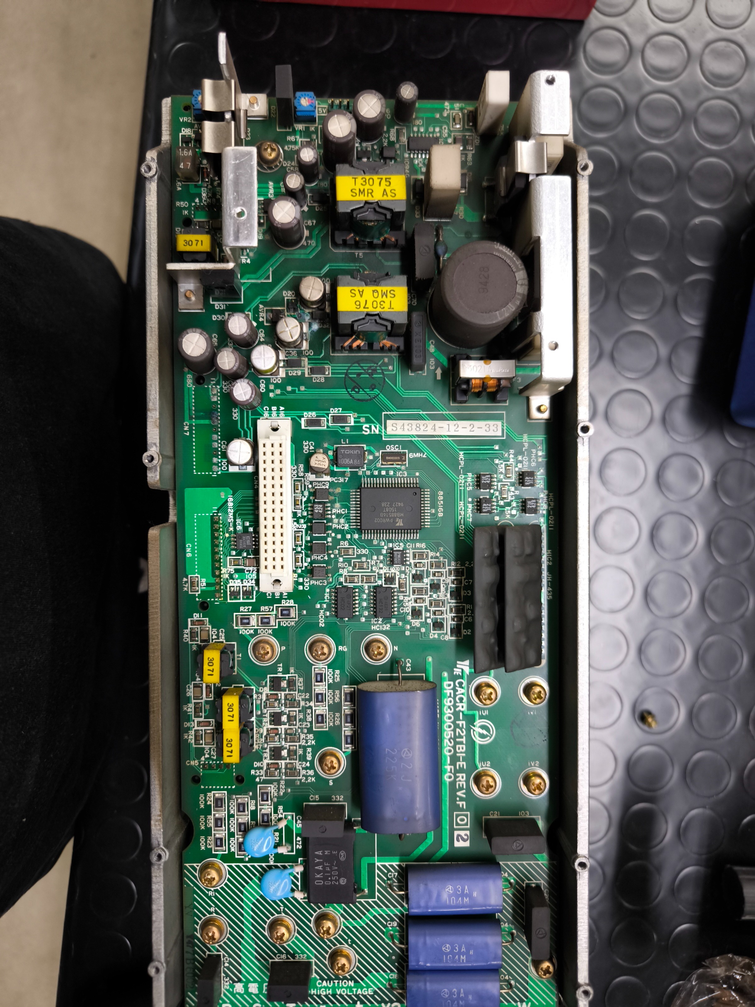
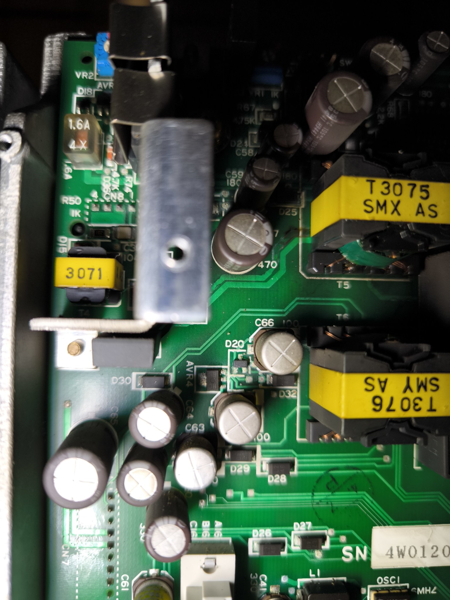
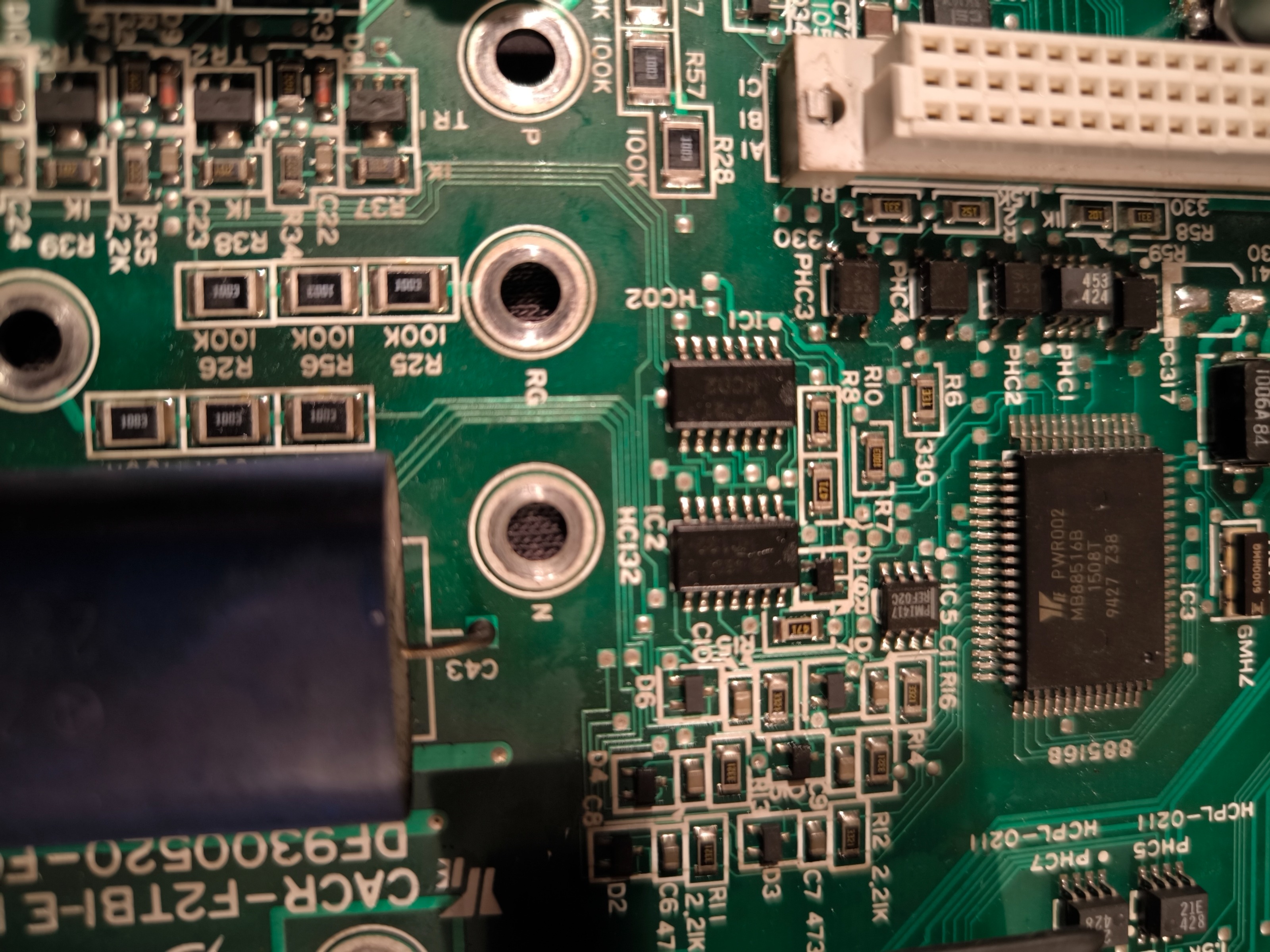
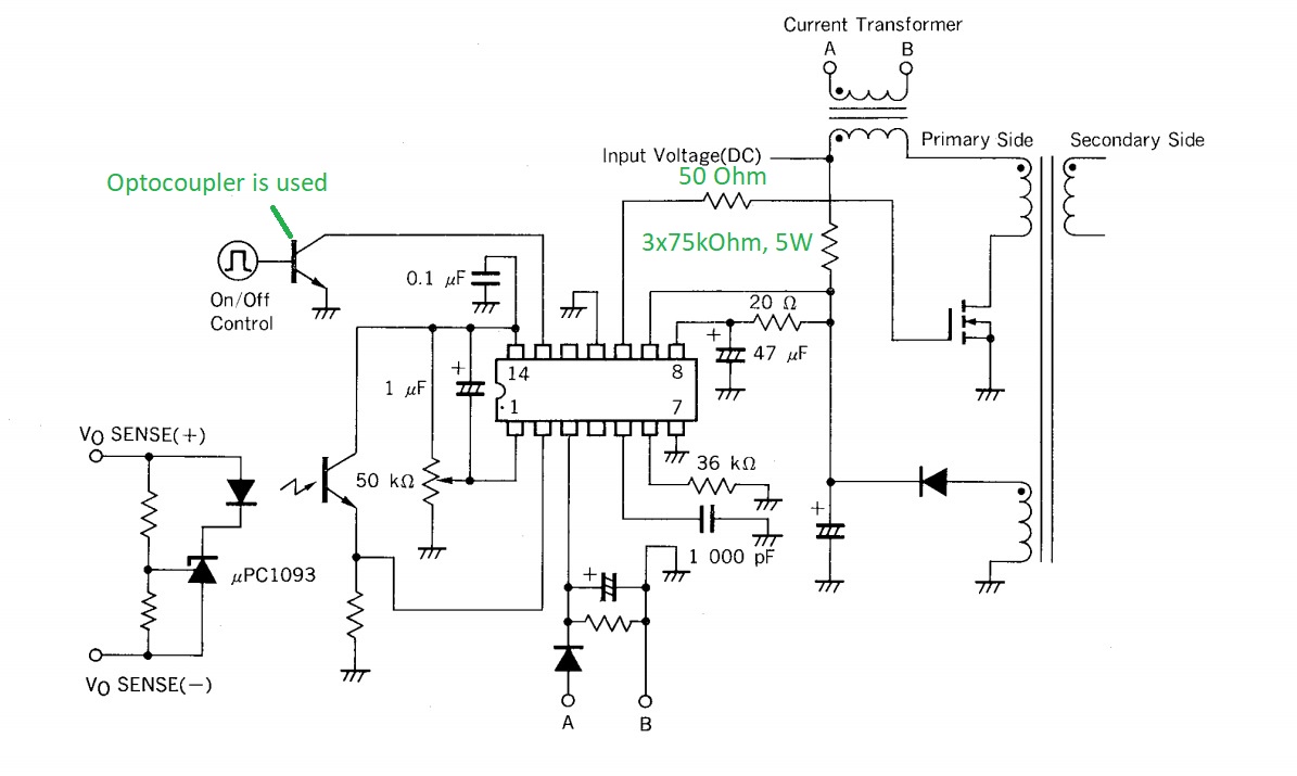
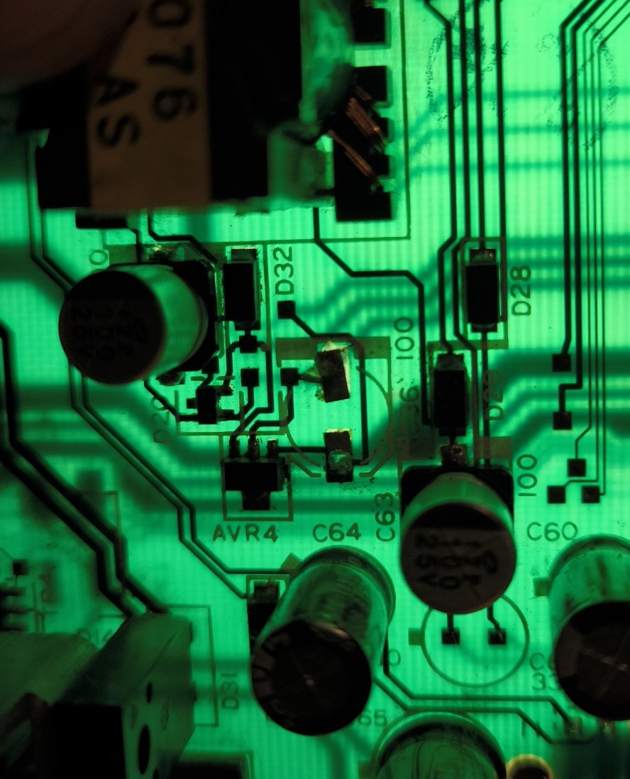 Hello everyone,I'm working on repairing a Yaskawa CACR-SR20BE12G-E servo drive. I initially had to replace all the capacitors as two of them had incorrect values, which was causing the A.02 error. After installing the board, everything worked fine for about 30 minutes, but then the auxiliary power supply errors A.03 and A.40 appeared.I've isolated the critical components after the transformer T3076, specifically D20 (code C3) and AVR4 (code 8C E4), which now appear to be faulty.I need help confirming the identity and replacement parts for these components.1. D20 (Code C3) - Raddrizzatore SchottkyI have traced the pinout of D20 and have the following connections:CENTER PIN: Connects to the positive pole of capacitor C41 33uf 25vTOP LEFT PIN: Connects to the transformer output, passing through diode D32.RIGHT PIN: Goes to the negative side of the board (or where the letter 'N' is marked).Question: Can anyone who has successfully repaired this confirm if the correct replacement is indeed the BAT54C (Dual Common Cathode, SOT-23)?2. AVR4 (Code 8C E4) -dimension(approx. 3x2mm). The marking on my faulty board is 8C E4, while a known working board shows 8C E8 (I assume the last digit is just a batch code).Pinout/Measurements:I'm using the following numbering: Pin 1 (Top Left), Pin 2 (Center), Pin 3 (Top Right), and Pin 4 (Bottom). Note that Pin 4 is common with Pin 2 on the board.Using the diode function on my multimeter:Black probe on Pin 2 or 4, Red probe on Pin 1 or 3 Reads 2.3v- 2.4VInverting the probes Reads 0.5 - 0.6V
Can you help me please?
Replied by nikopoli@live.it on topic Repair Servodrive Yaskawa CACR
Can you help me please?
Attachments:
Last edit: 14 Oct 2025 16:16 by nikopoli@live.it.
Please Log in or Create an account to join the conversation.
Time to create page: 0.157 seconds