Kerf Crossing / Anti Dive
- phillc54
-
 Topic Author
- Offline
- Platinum Member
-

- Posts: 5711
- Thank you received: 2100
These are just simplistic calculations to try explain my thoughts.
We know the length of each period in seconds:
period = 0.001We select a value for the maximum angle we expect to encounter, say 45 degrees.
This should be the greater of 1 or [AXIS_Z]MAX_VELOCITY * [AXIS_Z]OFFSET_AV_RATIO / [TRAJ]MAX_LINEAR_VELOCITY
ratio = 1We know the voltage change vs torch height. Rule of thumb here but this could be an entry for more exact calculation for those who have plotted their torch-height/voltage-change.
This would be in machine units:
units-per-volt = 0.1 (metric)
units-per-volt = 0.004 (the other one)
We check if the ratio is valid for the current velocity, if not then reduce it to suit:
if axis-maximum-velocity < current-velocity
    ratio = axis-maximum-velocity / current-velocity
We can calculate the distance travelled for the period:
distance-per-period = current-velocity * periodWe can then calculate what the maximum height change is that we could achieve for the period:
maximum-error-height = distance-per-period * ratioFinally we can calculate what the maximum voltage change could be for the period:
maximum-error-volts = distance-per-period * units-per-voltSo any voltage change above this for a period should lock THC.
Does this seem reasonable or am I on the wrong track?
Cheers, Phill.
Please Log in or Create an account to join the conversation.
- pl7i92
-

- Offline
- Platinum Member
-
- Posts: 1872
- Thank you received: 358
i will gove this a check as next week
but also on a G64 P0.3 it seams that the flow is quite good and the kerf is stable on edges
S-cutter Proma Thc
Please Log in or Create an account to join the conversation.
- rodw
-

- Offline
- Platinum Member
-
- Posts: 12047
- Thank you received: 4113
Its my understanding that most THC's monitor the change in voltage over time. This results in big numbers (as volts per second) eg:
(this_volts - last_volts)/ fperiodBut this value is several orders of magnitude higher when crossing a void than when normal servoing for torch height control. So if you calculate a dV/dT moving average of the last n readings (n might be 10, 100 or 1000 - to be determined), you have a slowly fluctuating smoothed benchmark to compare the current dV/dT for this servo period. I have not done enough samples to detemine a suitable threshold. A 1 volt change in a servo period results in a dV/DT of 1000 volts per second.
This plot I did shows clearly what happens when the data is reviewed in this manner and you can see how clearly the kerf cross is delineated.
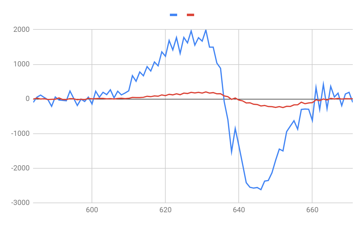
Note that this data is not in real time. I think there are 20 servo periods per tick on the horizontal axis. I really think this experiment needs to be repeated using halsampler and I think one cut will tell it all
Please Log in or Create an account to join the conversation.
- phillc54
-
Topic Author
- Offline
- Platinum Member
-
- Posts: 5711
- Thank you received: 2100
Rod,rodw wrote:
The correct variable to use is fperiod which is calculated each servo cycle and is in seconds
Yes, I am aware of that, I use fperiod in the plasmac component. They are just simplistic calculations to explain my reasoning.
Cheers, Phill.
Please Log in or Create an account to join the conversation.
- rodw
-
- Offline
- Platinum Member
-
- Posts: 12047
- Thank you received: 4113
patents.google.com/patent/US5866872
Review FIG. 3 carefully and you'll see similarities to what I observed leading up to my dV/dT approach.
If you wanted to explore a velocity based approach, I think you need to come up with an angle of the material at maximum warpage (2-3 degrees but I have no idea) and then calculate the change in voltage that could occur at the cut speed if the material was on that slope at the generally accepted 10 volts per mm, the inverse of 0.1 mm/volt. But then you need to allow for natural voltage fluctuations as the anode spot moves from the top surface (shortest distance, lowest voltage) to the bottom of the material.
So you'd come up with a formula something like
height_change = sine(theta) * (distance travelled per fperiod)
volts_change_threshold = cut_volts + height_change * change in volts per mm + anode_spot_voltage_variance + safe_margin
Where:
theta = maximum angle from warpage
Change in volts/mm = 10 (7.53v is what I measured)
anode spot voltage variance might be = say 1.2 volts (or your guess of what the normal voltage variance per period is.)
Safe_margin = your guess.(0.5-1 volt?)
Please Log in or Create an account to join the conversation.
- islander261
- Offline
- Platinum Member
-
- Posts: 757
- Thank you received: 216
You are months ahead of what I will be able to test shortly! I will need a new tut just to get it installed and configured let alone a new PP done.
Just a thought about the kerf crossing issue. I am not familiar with too many instances that one really wants to do chain cutting, maybe when cutting material that is over the pierce capability for your power supply which usually isn't common. The other thing I will point out is that when looping corners when cutting engineering work or leaving a cut with the correct length leadout you already are in a corner lock condition (usually) because the torch motion has slowed. I am finding with the Plasmac branch the default 90% of speed for the corner lock works fine. Just trying to save you all effort on corner conditions.
I believe that Rod's points are correct on the kerf crossing I tried to implement on my system. The voltage dV/dT is the start of the kerf crossing and is pretty good at detecting it. I did a hold time based on the velocity and kerf width from the cut parameters. Worked ok but I have really never needed it, the corner hold seems to catch all the times I would need a kerf crossing hold for now.
I am concerned about relying on the F[value from hal] (not the real code) to set the feed rate. As I recall this is only read at the start of the file before any motion. What if I change feed rates between cuts? Will this update correctly? Sorry I just don't know but do need to change feed rates between cuts on a work piece quite frequently.
John
Please Log in or Create an account to join the conversation.
- phillc54
-
Topic Author
- Offline
- Platinum Member
-
- Posts: 5711
- Thank you received: 2100
I shall keep persisting while I am receiving feedback.
John,
As long as you do the material change followed by the M66 P3 L3 Q1 then followed by the F word it will work correctly.
The M66 line ensures that the GUI has loaded the new material.
M190 P1
M66 P3 L3 Q1
F#<_hal[plasmac.cut-feed-rate]>1: the Fword display in Gmoccapy works correctly.
2: if you have a tool loaded then issue a Fnnn that is less than 99.9% of the cut-feed-rate of the loaded material then THC will be locked out.
Number 2 happens because plasmac uses the value of cut-feed-rate rather than motion.requested-velocity, so it uses this value for the complete cut.
I am very wary of remapping existing codes after seeing some of the side effects.
Cheers, Phill
Please Log in or Create an account to join the conversation.
- rodw
-
- Offline
- Platinum Member
-
- Posts: 12047
- Thank you received: 4113
What if I change feed rates between cuts? Will this update correctly?
John, in a sheetcam environment I'm guessing you might add some cutting rules on holes or arcs or the like. Could you use a feed override to slow the machine down instead of the F rate?
Really to change cutting speeds, you need to use another plasmac material. One thing that was cool to watch was the plasmac GUI being updated from my centre punch tool on a holes layer to the profile cutting tool on the M190.
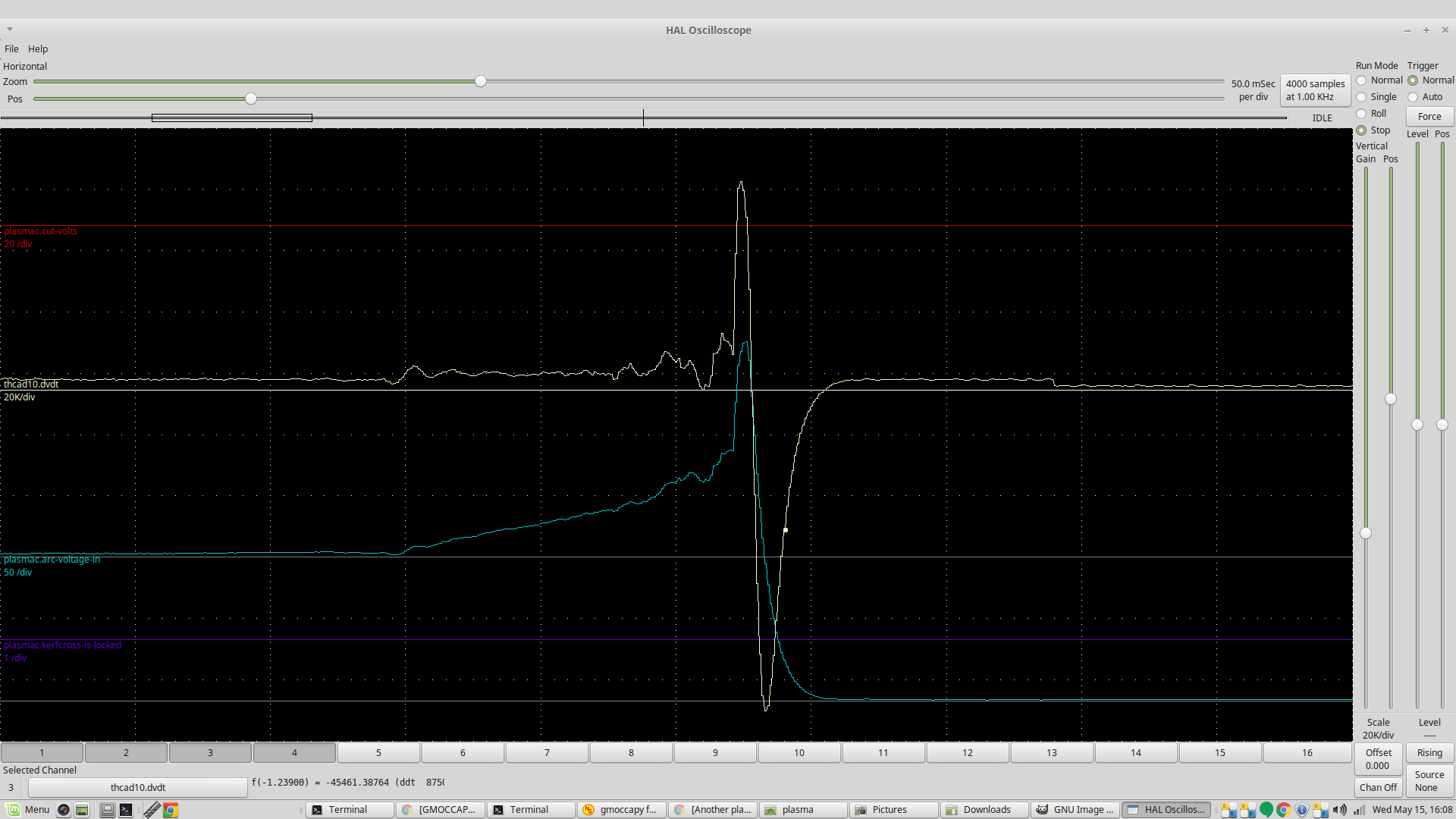
I posted this on the plasmac thread, but I guess it really belongs here dv/dt and torch voltage during a kerf cross
Please Log in or Create an account to join the conversation.
- rodw
-
- Offline
- Platinum Member
-
- Posts: 12047
- Thank you received: 4113
The normal cut was around 3300 up to 4000 very occasionally. So setting a dV/dT threshold of 5000 would catch a kerf crossing in 2 milliseconds. It would be hard to get better than that. White line is roughly at that 5000 threshold
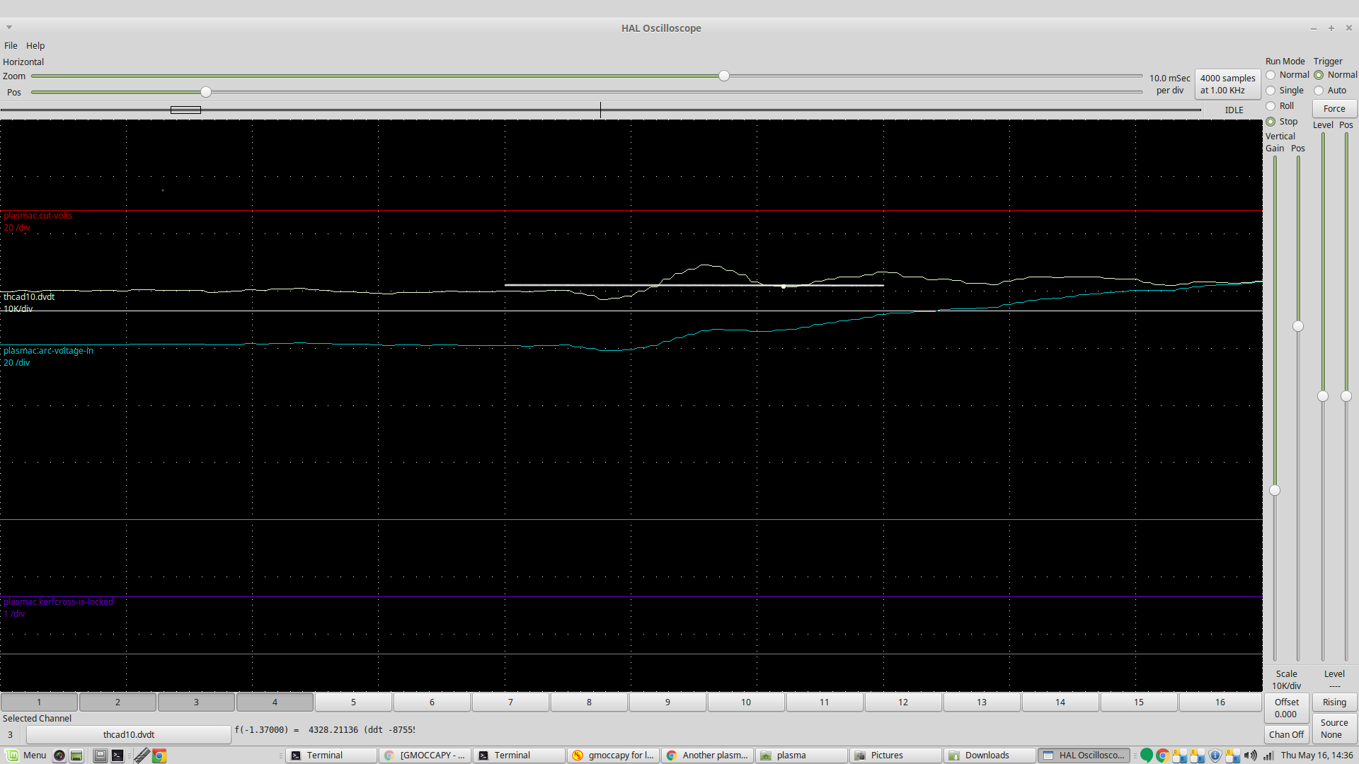
I'm not sure that the torch voltage approach would be any quicker and on the face of it, the 1 volt change required would be within normal expectations of a 1-2 volt cutting range.
Attachments:
Please Log in or Create an account to join the conversation.
- tommylight
-

- Away
- Moderator
-

- Posts: 21760
- Thank you received: 7435
Having used some very fast Z axis in the last few builds, the latter is very noticeable no matter what the thickness of the material, fortunately that never seems to cause any issues as if the part falls off there is plenty of room for the torch to move down without the risk of hitting anything, that is always the void between the slabs.
That brings another issue, finding the limit of what the maximum speed of cutting is and the maximum Change in voltage is while cutting the Maximum slope up and down with a really fast Z axis. Any change faster than that result could then be considered a kerf or a dive and lock the THC.
Rod, do you feel lucky?
") Could you please try to get some data at all the fastest your machine can do while cutting some thin 0.8 to 1mm sheet at say 45 degree slope and 30 to 50 Amps ? Nah that is to much I think but it would be nice.
Could you please try to get some data at all the fastest your machine can do while cutting some thin 0.8 to 1mm sheet at say 45 degree slope and 30 to 50 Amps ? Nah that is to much I think but it would be nice. Please Log in or Create an account to join the conversation.