Rods "Spaceship" Scratch built Plasma Cutter build
- rodw
-
 Topic Author
- Offline
- Platinum Member
-

Less
More
- Posts: 11953
- Thank you received: 4069
09 May 2019 20:57 #133292
by rodw
Replied by rodw on topic Rods "Spaceship" Scratch built Plasma Cutter build
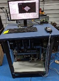
Grotius, thanks. I have upgraded to solid state relays on most circuits now as shown in the picture a few posts up. I've got a couple more mechanical ones to replace but have the parts here to do them. The hard thing is always to find something that is available and in stock in Australia.
The A120 inverter is working very nicely now I have ohmic sensing and clean dry air! The plasmac config is also working very well and has improved cut quality because of better height control. Actually, I am pretty amazed at the accuracy of the machine, M5 clearance holes in 2mm steel come out pretty much perfect!
I think its time to finish building my machine! I have a few little things to do in the control box and finish off the table.
Please Log in or Create an account to join the conversation.
- Grotius
-

- Offline
- Platinum Member
-
Less
More
- Posts: 2419
- Thank you received: 2348
09 May 2019 22:01 #133302
by Grotius
Replied by Grotius on topic Rods "Spaceship" Scratch built Plasma Cutter build
Rodw,
All info sounds very promising !!
A tiny problem your realised yourself, the current stock in Australia, to anticipate this in your current business model will
make you rich !
A good strike evolves most of time out of a problem.
" if there’s any way they can do it wrong, they will ". But inversing the law of Murphy will bring you luck !!
Please Log in or Create an account to join the conversation.
- rodw
-
Topic Author
- Offline
- Platinum Member
-
Less
More
- Posts: 11953
- Thank you received: 4069
15 May 2019 03:41 - 15 May 2019 03:46 #133809
by rodw
Replied by rodw on topic Rods "Spaceship" Scratch built Plasma Cutter build
Well I've had something really strange happen today that wasted a lot of time. Last night I upgraded to a later version of Plasmac before I went home. This involved making a copy of the new sim in my config folder, copying over my config files and updating the plasmac hal file with some changes to match my pinouts. Something I've done several times recently due to Phil's prolific updates!
This morning I was tidying up my workshop and I blew some compressed air into my control box to blow out the dust.
Then I went to use it.and the torch would not fire. So I checked physical wiring becasue of my clean up and it seemed OK so I check in HALshow to see the plasmac component torch on signal was properly configured and working. The component signal fired as per normal but the physical 7i76e pin did not light up even though halshow showed that they were connected! Assuming I'd broken something I changed HAL to point to a different spare pin. Still not working. SO I wondered then if the TB6 output pins were fried so I moved to another spare output on TB5 and still nothing happened.
So in desperation I tried yesterdays's config and it worked Then I got half way through writing this and it dawned on me, the pin could not be connected to a signal. And sure enough, that was the fault. I had commented out one line too many! so the moral of the story is to check everything works straight after you change your config while everything is fresh in your mind, not the next day!
Anyway for a reward for reading this far, here is a demo of the auto height control in plasmac!
Last edit: 15 May 2019 03:46 by rodw.
The following user(s) said Thank You: phillc54
Please Log in or Create an account to join the conversation.
- docwelch
- Offline
- Senior Member
-

Less
More
- Posts: 58
- Thank you received: 25
16 May 2019 12:58 #133963
by docwelch
Replied by docwelch on topic Rods "Spaceship" Scratch built Plasma Cutter build
Rod and/or John,
Back on page 32 of this thread, John posted a schematic of his wiring. I noticed that he uses a relay to power/depower the limit switches and estop. What is the reason behind this? Based on the fact you both have working machines, I'm pretty sure there's a reason for doing it this way but I haven't been able to see the benefit(s).
Thanks,
Steven
Please Log in or Create an account to join the conversation.
- rodw
-
Topic Author
- Offline
- Platinum Member
-
Less
More
- Posts: 11953
- Thank you received: 4069
16 May 2019 13:29 #133969
by rodw
Steven, I'm not sure about John's ideas but I keep all my limit sensors powered up. My understanding is an estop should drop all motive power so my estop cuts mains power to the stepper motor power supply and also drops mains power to the ohmic sensing circuit as it is connected direct to the table frame. When I get there, it will also drop power to the downdraft fan.
I've attached the ohmic sensing circuit I use. It differs from John's as it only has one diode (the second one caused an induced voltage between the table frame and ohmic clip somehow. I also only have single pole relays so use two where John used one to isolate the ohmic sensor.
Over time, I ended up with 3 estops and it was not possible to wire them all into a mains powered circuit so I joined them in Hal using the estop-chain which fires a relay that disables the stepper motors on an estop (which is handy if you are on a limit and want to manually move off it.)
Replied by rodw on topic Rods "Spaceship" Scratch built Plasma Cutter build
Rod and/or John,
Back on page 32 of this thread, John posted a schematic of his wiring. I noticed that he uses a relay to power/depower the limit switches and estop. What is the reason behind this? Based on the fact you both have working machines, I'm pretty sure there's a reason for doing it this way but I haven't been able to see the benefit(s).
Thanks,
Steven
Steven, I'm not sure about John's ideas but I keep all my limit sensors powered up. My understanding is an estop should drop all motive power so my estop cuts mains power to the stepper motor power supply and also drops mains power to the ohmic sensing circuit as it is connected direct to the table frame. When I get there, it will also drop power to the downdraft fan.
I've attached the ohmic sensing circuit I use. It differs from John's as it only has one diode (the second one caused an induced voltage between the table frame and ohmic clip somehow. I also only have single pole relays so use two where John used one to isolate the ohmic sensor.
Over time, I ended up with 3 estops and it was not possible to wire them all into a mains powered circuit so I joined them in Hal using the estop-chain which fires a relay that disables the stepper motors on an estop (which is handy if you are on a limit and want to manually move off it.)
The following user(s) said Thank You: docwelch
Please Log in or Create an account to join the conversation.
- bevins
-
- Offline
- Platinum Member
-
Less
More
- Posts: 1942
- Thank you received: 338
16 May 2019 15:00 #133981
by bevins
Replied by bevins on topic Rods "Spaceship" Scratch built Plasma Cutter build
Great work all on this plasmac. I cant wait to get to that point. Rodw, can you give me part numbers on your ohmic sensor?
The following user(s) said Thank You: rodw
Please Log in or Create an account to join the conversation.
- islander261
- Offline
- Platinum Member
-
Less
More
- Posts: 757
- Thank you received: 216
16 May 2019 18:07 #133991
by islander261
Replied by islander261 on topic Rods "Spaceship" Scratch built Plasma Cutter build
docwelch
The estop interlock relay is how my commercial mill is wired. Now that I have used actually used LinuxCNC on a working machine for a bit over a year I don't think it is necessary but it does make for a nice check because until you come out of estop all the indicators are active.
Rod
I know you don't want to hear this again. If just removing the protection diode fixes your probing indicator you have a ground fault in your "floating" power supply circuit some place. This isn't ideal but just goes to show how good the 7i76E is.
To find the ground fault:
1. Disconnect all output connections on the "floating" power supply.
2. Connect a volt meter between the floating power supply +output and your table frame/slats (or the safety ground in your electronics cabinet).
3. Turn on your electronics cabinet and read voltage on meter. it should be very near zero.
4. Move the meter lead from "floating" power supply +output to "floating" power supply -output. It should be very near zero.
5. Intermediate results. If 3 and 4 both read near zero fault is most likely not in power supply. If 3 or 4 reads voltage near power supply output in absolute value there is a problem in the power supply.
6. Turn off electronics cabinet and wait for power supply output caps to discharge (have a coffee).
7. Set meter to ohms reading. Connect one lead to floating power supply -output and the other to table frame/slats (or the safety ground in your electronics cabinet). Read meter. Reverse leads and read meter.
8. Same as 7 but connect meter lead to floating power supply +output. You may see meter go from low ohms to high ohms here and that is ok.
9. Any reading below 100k ohms ( in industrial work we would be looking for over 1meg at 100v here) on either 7 or 8 indicates a fault in the power supply.
10. If none of the above yields a fault indication then the problem is in your wiring or other component. With the power still off and the external circuitry disconnected from the power supply use your meter on the ohms setting to check each node in your wiring until you find the fault.
The most likely problem is the the -output on the power supply is connected to safety ground (DIN rail clamp) internally in the power supply. The manufactures do this with cheap switch mode power supplies so they can meet EMI codes without adding more expensive filters. A less likely problem is that the ac neutral connection is connected to safety ground for the same reason.
Good Luck
John
The following user(s) said Thank You: docwelch
Please Log in or Create an account to join the conversation.
- bevins
-
- Offline
- Platinum Member
-
Less
More
- Posts: 1942
- Thank you received: 338
16 May 2019 18:36 - 16 May 2019 18:46 #133993
by bevins
The power supply for the ohmic sensor relays, is this the same power supply that's used for field power?
Looking at this further I am thinking I am better off with an ethernet mesa card instead of the 5i25.
Replied by bevins on topic Rods "Spaceship" Scratch built Plasma Cutter build
docwelch
Rod
I know you don't want to hear this again. If just removing the protection diode fixes your probing indicator you have a ground fault in your "floating" power supply circuit some place. This isn't ideal but just goes to show how good the 7i76E is.
Good Luck
John
The power supply for the ohmic sensor relays, is this the same power supply that's used for field power?
Looking at this further I am thinking I am better off with an ethernet mesa card instead of the 5i25.
Last edit: 16 May 2019 18:46 by bevins.
Please Log in or Create an account to join the conversation.
- islander261
- Offline
- Platinum Member
-
Less
More
- Posts: 757
- Thank you received: 216
16 May 2019 18:46 #133994
by islander261
Replied by islander261 on topic Rods "Spaceship" Scratch built Plasma Cutter build
Bevins
One of the Ethernet cards is a much more conservative design path for a plasma cutter.
The isolated power supply for probing is only used for the probing circuit it is not the same as your field power for the rest of your I/O. When used with good galvanic isolation, opto module, relay(s), you never have conductive connection between your control electronics and the table chassis or work piece.
John
The following user(s) said Thank You: bevins
Please Log in or Create an account to join the conversation.
- docwelch
- Offline
- Senior Member
-
Less
More
- Posts: 58
- Thank you received: 25
16 May 2019 19:10 #133995
by docwelch
Replied by docwelch on topic Rods "Spaceship" Scratch built Plasma Cutter build
Rod,
Thanks for the information and circuit drawing. I've been playing around with some ideas myself and have attached what I plan to use for the ohmic sensing circuit. Interestingly, I found some single chip SSRs ($2.16 each) that I think will work well for this project. I also have a circuit for ohmic sensing that will allow you to adjust the sensitivity so that less than optimal metal could be detected (maybe overkill and not needed). I'm using an optocoupler to send the final signal back to the control board as it has a much quicker response time (10uS) than the SSRs (0.3 - 1.0 mS). It's also probably overkill for the probing speeds that are used.
John,
Thanks for the information about the estop circuitry.
Steven
Please Log in or Create an account to join the conversation.
Time to create page: 0.513 seconds