rectangle3 for mill / router
- Rick G
-
 Topic Author
- Offline
- Junior Member
-

Less
More
- Posts: 27
- Thank you received: 155
22 Sep 2013 15:12 - 01 Feb 2015 16:23 #39101
by Rick G
rectangle3 for mill / router was created by Rick G
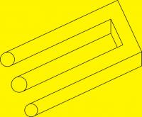
For rectangles on the mill / router with square or radius corners.
Uses cutter radius compensation, multiple pass for deep cut.
Rectangle can be rotated.
Cuts inside or outside of path, clockwise or counter clockwise tool path.
Location of rectangle set with X start and Y start.
X start Y start is lower left of rectangle before any rotation
Select Main and Temp coordinate systems.
Uses check_cord3.ngc and M110
Newer version below.
Rick G
Last edit: 01 Feb 2015 16:23 by Rick G. Reason: Newer version below
The following user(s) said Thank You: Mike_Eitel, BigJohnT
Please Log in or Create an account to join the conversation.
- BigJohnT
-

- Offline
- Administrator
-

Less
More
- Posts: 6999
- Thank you received: 1176
22 Sep 2013 17:52 #39105
by BigJohnT
Replied by BigJohnT on topic rectangle3 for mill / router
Pretty neat Rick,
I really need to get a probe built for my mill...
JT
I really need to get a probe built for my mill...
JT
Please Log in or Create an account to join the conversation.
- johns00056
- Offline
- Premium Member
-

Less
More
- Posts: 110
- Thank you received: 2
01 Feb 2015 04:02 #55524
by johns00056
Replied by johns00056 on topic rectangle3 for mill / router
I can't get this one to work.
( Actually I can't get any of the NGCGUI programs to work, but I thought that I would start with this one)
The error message is- length of cutter compensation move is not greater than tool radius.
I want to start in the middle and mill an inside rectangle.
I have tried a bunch of starting positions, but it only works if the tool diameter is 0.
Also- I don't know what #17 (= 54 Main G cord) and #18 (=55 Temp G cord) are.
Please Log in or Create an account to join the conversation.
- Rick G
-
Topic Author
- Offline
- Junior Member
-
Less
More
- Posts: 27
- Thank you received: 155
01 Feb 2015 16:20 #55544
by Rick G
Replied by Rick G on topic rectangle3 for mill / router
Here is a newer version, This one you reference from the center of the rectangle.
#17 and #18 are the coordinate systems to use for the sub.
On a mill you might have more than one vise or work area, the first uses say coordinate systems 54 and 55, the second may use 56 and 57. If you always work in 54 just ignore them.
Rick G
#17 and #18 are the coordinate systems to use for the sub.
On a mill you might have more than one vise or work area, the first uses say coordinate systems 54 and 55, the second may use 56 and 57. If you always work in 54 just ignore them.
o<rectangle33> sub

; rectangle3 for mill to cut rectangles with square or radius corners. Uses cutter radius compensation, multiple pass for deep cut.
; Cuts inside or outside of path, clockwise or counter clockwise tool path.
; Location of rectangle set with X start and Y start.

;X_start Y_start is the center of rectangle

; Rectangle can be rotated.
; Select Main and Temp coordinate systems.
; uses check_cord3.ngc and M110
; from office 12/28/13


(UNTESTED CONCEPT ONLY, EDIT AND TEST BEFORE USING)

#<x_length>	=    #1 (= 4 X length)
#<y_length>	=    #2 (= 2 Y length)

#<x_center>	=     #3 (=  X center)
#<y_center>	=     #4 (=  Y center)

#<z_start>	=     #5 (= .010 Z start)
#<rotate>	=      #6 (= 0 Angle)
#<Corner_Rad>	=  #7 (= 0 Corner Radius)
#<Depth> =       #8 (= .20 Depth)
#<z_safe> =      #9 (= .25 Z safe)
#<z_rate> =      #10 (= 10 Plunge rate)
#<z_step> =      #11 (= .025 Z step)
#<Feed_rate> =   #12 (= 100 Feed rate)
#<clockwise> =   #13 (= 1 Clockwise 1 , CCW 0)
#<Tool_no>	 =    #14 (= 2 Tool Number)
#<Inside>	 =     #15 (= 1 Inside 1, Outside 0)
#<RPM>		 =       #16 (= 500 Spindle RPM)
#<Main_cord> =   #17 (= 54 Main G cord)
#<Temp_cord> =   #18 (= 55 Temp G cord)

G17 (xy plane)
G20 (inches)
G40 (cancel cutter radius compensation)
G49 (cancel tool length offset)
G90 (absolute distance mode)
G94 (units/min feed rate)
G64 P.001 Q.001 (set path tolerance)

;set global parameters
#<_m:cord> = 0
#<_t:cord> = 0

o201	if [[#<Inside> LT 0] OR [#<Inside> GT 1]]
	(debug, bad Inside input, must be 1 for inside or 0 for Outside #<Inside>)
         o200 return
o201   endif

o301	if [#<Corner_Rad> LT 0]
	(debug, bad Corner Radius input, must be 0 or greater #<Corner_Rad>)
        o300 return
o301   endif

o311	if [[[#<Corner_Rad> * 2] GT #<x_length>] OR [[#<Corner_Rad> * 2] GT #<y_length>]]
	(debug, Corner Radius too large for path Corner radius #<Corner_Rad>,)
        o310 return
o311   endif

o401	if [#<Depth> LT 0]
	(debug, bad Depth input, must be 0 or greater #<Depth>)
         o400 return
o401   endif

o501	if [[#<clockwise> LT 0] OR [#<clockwise> GT 1]]
	(debug, bad clockwise input, must be 1 for clockwise or 0 for counterclockwise #<clockwise>)
         o500 return
o501   endif

o601	if [#<z_step> LE 0]
	(debug, bad Z step, must be greater than 0  #<z_step>)
	       o600 return
o601  endif

o701	if [#<Temp_cord> EQ #<Main_cord>]
	(debug, Main cord and temp cord cannot be the same Main #<Main_cord> Temp #<Temp_cord>)
	o700 return
o701   endif

o<check_cord3> call [#<Main_cord>] [#<Temp_cord>]

#<Main_cord_n> = #<_m:cord>
#<Temp_cord_n> = #<_t:cord>

;reset global parameters
#<_m:cord> = 0
#<_t:cord> = 0

o801	if [#<Temp_cord_n> EQ 0]
	(debug, bad Temp cord #<Temp_cord_n>)
	o800 return
o801   endif

o901	if [#<Main_cord_n> EQ 0]
	(debug, bad Main cord #<Main_cord_n>)
	o900 return
o901   endif

(debug, Main cord #<Main_cord> and #<Main_cord_n>)
(debug, Temp cord #<Temp_cord> and #<Temp_cord_n>)

G#<Main_cord>

#<x_length>=[#<x_length> - [#<Corner_Rad> * 2]]
#<y_length>=[#<y_length> - [#<Corner_Rad> * 2]]

#<x_start> = [#<x_length> / 2]
#<y_start> = [#<y_length> / 2]

#<Cut_Amount> = [#<Depth> + #<z_start>] ; deepest Z cut
#<Cuts> = FUP [[#<Cut_Amount> /  #<z_step>]] ; round up the number of passes to reach deepest cut
#<z_step> = [#<Cut_Amount> / #<Cuts>] ; amount to take off Z each pass

F#<Feed_rate>
M6 T#<Tool_no>
M3 (spindle on forward)
G4 P.2 (pause for spindle to reach speed)
G0 Z#<z_safe>
G0 X#<x_center> Y#<y_center> (go to center location)
(debug, go to center location X #<x_center> Y #<y_center>)
(debug, x start #<x_start> y start #<y_start>)
G4 P2

G10 L20 P#<Temp_cord_n> X0 Y0 Z#<z_safe> (set Temp cord)
G#<Temp_cord>
G10 L2 P#<Temp_cord_n> R#<rotate> (rotate for angle G_temp)
G0 X-#<x_start>  Y-[#<y_start> + #<Corner_Rad>]
G91 (relative distance mode)

o<c100> if [#<clockwise> EQ 1]
	o<i100> if [#<Inside> EQ 0] (cut offset to inside path)
		G41 D#<Tool_no>
	o<i100> endif

	o<i200> if [#<Inside> EQ 1] (cut offset to outside of path)
		G42 D#<Tool_no>
	o<i200> endif

	G0 X#<x_length>
	G90 (absolute distance mode)
	G0 Z[#<z_start> + .025]
	G1 Z#<z_start>F#<z_rate>
	G91 (relative distance mode)
	F#<Feed_rate>

o<z100> while [#<Cuts>]
	o<r1100> if [#<Corner_Rad> GT 0]
	  G1 X-#<x_length>Z-#<z_step>
	  G2 X-#<Corner_Rad> Y#<Corner_Rad> R#<Corner_Rad>
	  G1 Y#<y_length> ;up
	  G2 X#<Corner_Rad> Y#<Corner_Rad> R#<Corner_Rad>
	  G1 X#<x_length> ;right
	  G2 X#<Corner_Rad> Y-#<Corner_Rad>R#<Corner_Rad>
	  G1 Y-#<y_length>
	  G2 X-#<Corner_Rad> Y-#<Corner_Rad> R#<Corner_Rad>
 	o<r1100> else
    		G1 X-#<x_length>Z-#<z_step>
	    	G1 Y#<y_length> ;up
	    	G1 X#<x_length> ;right
     	G1 Y-#<y_length>
	o<r1100> endif
	#<Cuts> = [#<Cuts> - 1]
o<z100> endwhile ;Cuts
G1 X-[#<x_length> -  #5401]

o<c100> else ;counter clockwise
	o<i1100> if [#<Inside> EQ 0] (cut offset to inside path)
	G42 D#<Tool_no>
	o<i1100> endif
 	o<i2200> if [#<Inside> EQ 1] (cut offset to outside of path)
	 G41 D#<Tool_no>
	 o<i2200> endif
 G0 X[#5401 *2]
 G0 X-[#5401 *2]
 G90
 G0 Z[#<z_start> + .025]
 G1 Z#<z_start>F#<z_rate>
 G91
 F#<Feed_rate>
   o<z200> while[#<Cuts>]
    o<r100> if [#<Corner_Rad> GT 0]
    	 G1 X#<x_length>Z-#<z_step>
	     G3 X#<Corner_Rad> Y#<Corner_Rad> R#<Corner_Rad>
	     G1 Y#<y_length> ;up
	     G3 X-#<Corner_Rad> Y#<Corner_Rad>R#<Corner_Rad>
	     G1 X-#<x_length> ;left
	     G3 X-#<Corner_Rad> Y-#<Corner_Rad>R#<Corner_Rad>
	     G1 Y-#<y_length> ;down
	     G3 X#<Corner_Rad> Y-#<Corner_Rad>R#<Corner_Rad>
       o<r100> else
		       G1 X#<x_length>Z-#<z_step>
	       	G1 Y#<y_length> ;up
		       G1 X-#<x_length> ;left
		       G1 Y-#<y_length> ;down
      o<r100> endif
    #<Cuts> = [#<Cuts> - 1]
  o<z200> endwhile ;Cuts
		G1 X[#<x_length> -  #5401]
 o<c100> endif
G90
G0 Z#<z_safe>
G40
G10 L2 P#<Temp_cord_n> R0 (reset rotate)
G#<Main_cord>
M5
M110 (clear messages)
o<rectangle33> endsub
Rick G
Please Log in or Create an account to join the conversation.
- johns00056
- Offline
- Premium Member
-
Less
More
- Posts: 110
- Thank you received: 2
01 Feb 2015 22:25 - 02 Feb 2015 06:53 #55551
by johns00056
Replied by johns00056 on topic rectangle3 for mill / router
Thanks for the response.
It still only works if the tool diameter is zero.
It is a cool program and I can just use it without cutter diameter compensation.
It still only works if the tool diameter is zero.
It is a cool program and I can just use it without cutter diameter compensation.
Last edit: 02 Feb 2015 06:53 by johns00056.
Please Log in or Create an account to join the conversation.
- Rick G
-
Topic Author
- Offline
- Junior Member
-
Less
More
- Posts: 27
- Thank you received: 155
02 Feb 2015 17:09 #55574
by Rick G
Replied by Rick G on topic rectangle3 for mill / router
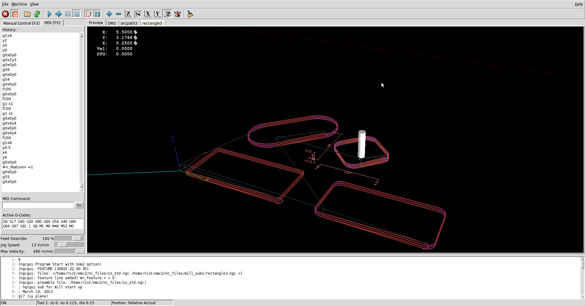
Perhaps you can give a little more detail on what you are trying to do, and what is happening.
Size of rectangle, location, starting point, tool size, metric/inch, (the sub is set for inch) etc.
Try setting it up with a larger rectangle and or smaller tool.
Seems to works fine here on sim.
Rick G
Size of rectangle, location, starting point, tool size, metric/inch, (the sub is set for inch) etc.
Try setting it up with a larger rectangle and or smaller tool.
Seems to works fine here on sim.
Rick G
Please Log in or Create an account to join the conversation.
- andypugh
-

- Offline
- Moderator
-

Less
More
- Posts: 23451
- Thank you received: 4987
02 Feb 2015 21:22 #55581
by andypugh
I suspect you might be getting tangled up with a mm pocket and something assuming an inch tool diameter.
Replied by andypugh on topic rectangle3 for mill / router
It still only works if the tool diameter is zero
I suspect you might be getting tangled up with a mm pocket and something assuming an inch tool diameter.
Please Log in or Create an account to join the conversation.
- johns00056
- Offline
- Premium Member
-
Less
More
- Posts: 110
- Thank you received: 2
02 Feb 2015 22:07 - 02 Feb 2015 22:38 #55584
by johns00056
Replied by johns00056 on topic rectangle3 for mill / router
Thank you, I really appreciate the help.
It still will not work even with a tool diameter as small as .001 inch ,or a rectangle as large as 100 inches.
I am feeding counter clockwise, inside.
If the tool diameter is zero,the plot displays OK in Axis, with the tool feeding z minus straight down to the starting point at the beginning of the first straight segment.
I would think that the spindle center line needs to be away from the start of the first segment by 1/2 the cutter diameter before the cutter diameter compensation is applied.
I am not going to spend any more time on this right now.
Last edit: 02 Feb 2015 22:38 by johns00056.
Please Log in or Create an account to join the conversation.
Time to create page: 0.101 seconds